
This article shows you how to build a fully functional Geiger Counter capable of measuring the three primary forms of radiation*; alpha, beta and gamma radiation. The geiger counter is sensitive enough to detect background radiation. It's expandable. You can enhance the basic Geiger Counter by adding a Digital Meter Adapter (DMAD) that adds a digital output for the Counts Per Second (CPS). The DMAD when used with a USB TTL adaptor can use our free Windows Radiation monitoring program . The DMAD also has a true Random Number Generator function. The windows XP radiation program is free and available for downloading here.
The Geiger Counter produces an audible click and blinks a LED each time it detects a radioactive particle. It has a Data output jack, that outputs a +5V pulse everythime a radioactive particle is detected. It also has a headphone jack for private listening. Typically the Geiger counter clicks 10-20 times a minute due to normal background radiation. While the device is sensitive enough to measure background radiation, it is not suitable for measuring radon gas. There are Radon gas detectors that use an activated charcoal filter that are easy to use and more accurate.
*Using GMT-01 (LND-712).
When using GMT-02, Geiger counter can only detect beta, x-ray and gamma
Radioactivity
Radioactivity is the spontaneous emission of energy from the nucleus of certain atoms. The most familiar radioactive material is uranium.
There are three forms of energy associated with radioactivity; alpha, beta and gamma radiation. The classifications were originally determined according to the penetrating power of the radiation, see Figure 1. Our Geiger Counter can detect the three types of radiation; alpha, beta and gamma radiation.
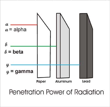
Alpha radiation are the nuclei of helium atoms, two protons and two neutrons bound together. Alpha rays have a net positive charge. Alpha particles have weak penetrating ability, a couple of inches of air or a few sheets of paper can effectively block them.
Beta radiation were found to be electrons, identical to the electrons found in atoms. Beta rays have a net negative charge. Beta rays have a greater penetrating power than Alpha rays and can penetrate 3mm of aluminum.
Gamma radiation are high-energy photons. This has the greatest penetrating power being able to pass through several centimeters of lead and still be detected on the other side. Thick lead is needed to attenuate gamma radiation.
Detecting Radiation - The Geiger Mueller Tube
A cut away drawing of a typical Geiger Mueller (GM) tube is shown in Figure 2. The wall of the GM tube is a thin metal (cathode) cylinder surrounding a center electrode (anode). The metal wall of the GM tube serves as the cathode of the GM Tube. The front of the tube is a thin Mica window sealed to the metal cylinder. The thin mica window allows the passage and detection of the weak penetrating alpha particles. The GM tube is first evacuated then filled with Neon, Argon plus Halogen gas.
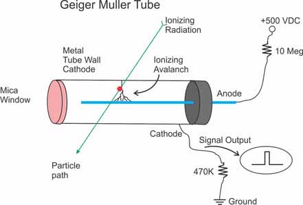
Our GM tube is put into an initial state (ready to detect a radioactive particle), by applying + 500-volt potential to the anode (center electrode) through a ten mega ohm current limiting resistor. A 470K-ohm resistor is connected to the metal wall cathode of the tube and to ground. The top of the 470K resistor is where we see our pulse signal whenever a radioactive particle is detected.
In this initial state the GM tube has a very high resistance. However, when a radioactive particle passes through the GM tube, it ionizes the gas molecules in its path and creates a momentary conductive path in the gas. This is analogous to the vapor trail left in a cloud chamber by a particle. In the GM tube, the electron liberated from the atom by the particle, and the positive ionized atom both move rapidly towards the high potential electrodes of the GM tube. In doing so they collide with and ionize other gas atoms, creating a momentary avalanche of ionized gas molecules. And these ionized molecules create a small conduction path allowing a momentary pulse of electric current to pass through the tube allowing us to detect the particle.
This momentary pulse of current appears as a small voltage pulse across the 470 K ohm resistor. The halogen gas quickly quenches the ionization and the GM tube returns to its high resistance state ready to detect more radioactivity.
Radiation Measurement - GM Tube's Dead Time
For the short amount of time the GM tube is detecting one particle, if another radioactive particle enters the tube it will not be detected. This is called dead time. The maximum dead time for our GM tube is 90 microseconds (or .00009 seconds). There is a mathematical formula for adjusting a Geiger counter read out to compensate for the GM tube's dead time. However the adjust is so small that for practical applications it can be ignored. High-end nuclear work will take a tube's dead time into consideration.
Count Rate vs. Dose Rate
Each output pulse from the GM tube is a count. The counts per second give an approximation of the strength of the radiation field. The GM tube has been calibrated using a cesium-137. The chart is shown in Figure 3.
Figure 3. Chart detailing Count Rate vs. Dose Rate
Geiger Counter Schematic
The circuit is shown in Figure 4. The 4049 Hex Inverting Buffer is set up as a square wave generator. The power MOSFET IRF830 switches the current on and off to the primary windings of the mini step-up transformer. The output of the mini step-up transformer is fed to a voltage doubler consisting of two high voltage diodes D4 and D5 and two high voltage capacitors C3 and C4.
The high voltage output from this stage is regulated to 500 volts needed for our GM tube, *GMT-01 (LND 712) by three zener diodes stacked one on top of the other (D6, D7 and D8). Diodes D7 and D8 are 200V zener diodes and diode D6 is a 100-Volt zener. Together (200 + 200 + 100 = 500), they equal 500 volts. Five hundred volts is the optimum operating voltage for our GM Tube.
The 500-volt regulated output is fed to the anode of the LND 712 GM tube through a current limiting 10 mega-ohm resistor R16. The 10 mega-ohm resistor limits the current through the GM tube and helps quench the avalanched ionization when a radioactive particle is detected.
*To regulate to the 400 volts needed for the GMT-02 Tube, a jumper is placed on P10. THis jumps the 100-volt zener diode at D6. R16 becomes a 2.2 mega-ohm resistor when using the GMT-02.
The cathode of the tube is connected to a 5.1V (D2) Zener diode. The voltage pulse across D2 generated by the detection of radiation, feeds to the base of a 2N3904 NPN transistor.
The NPN transistor clamps the output pulse from the GM tube to Vcc and feeds it to a comparator gate on the LM339. The pulse signal from the gate, pin 14 of the LM339, is a trigger to the 555 Timer through Q4. The timer is set up in monostable mode that stretches out the pulse received on its trigger. The output pulse from the timer flashes the LED and outputs an audible click to the speaker via pin 3.
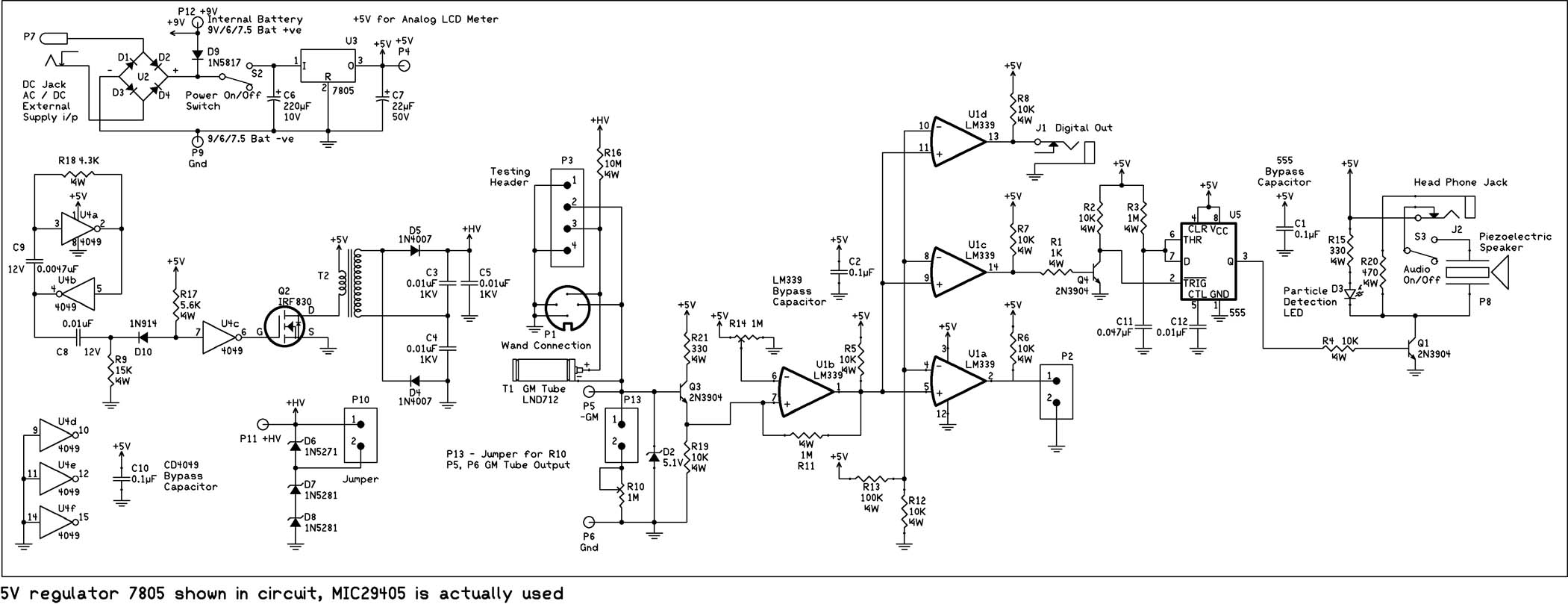
Figure 4. Circuit Schematic
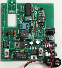
PC Board Construction
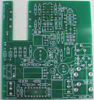
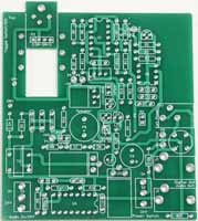
Figure 5A. Detail of top silkscreen on PCB (for GMT-01 or internal tube)
Figure 5B. Detail of top silkscreen on PCB (for GMT-02 or external wand)
You may hardwire this circuit to a breadboard or use the available PCB board. Although you do not need the PCB, the PCB will may construction easier. The top silkscreen of the PCB is shown in Figure 5. Begin construction by soldering resistors R17 5.6K (color bands green, blue, red), R18 4.3K (color bands yellow, orange, red) and R9 15K (color bands brown, green, orange). Next we will wire the square wave generator and pulse shaping circuit using the ICS-16 socket for the 4049, marked U4 on PCB. Insert the ICS-16, making sure to orient the notch on socket to the drawing on the PCB and solder to the board.
Place and solder components C8 (.01uf), C9 (.0047uf), C10, (.1uf) and D10 (1N914). Now construct the high voltage section consisting of the step up transformer T2, diodes D4 & D5 (1N4007) and capacitors C3, C4 and C5 (.01uf 1KV). Mount IRF830 transistor Q2 to the PCB, bend the transistor outward so it lays flat on the PCB, see Figure 6, and solder.
To this add the 5 volt 7805 regulator (U3), bending it outward so it lays flat as with transistor and solder into position. Next mount and solder capacitors C6 (220uf-330uf), C7 (22uf), and diode D9 (1N5817). Place and solder the 9-volt battery cap on the PC board. The red lead connects to the positive terminal P12. The black lead connects to GND, marked P9. Solder the power switch to the PCB at S2. Insert 4049 into the socket, making sure to orient the notch on the chip to the notch on the socket.
Testing HV Section
CAUTION: Circuit generates high voltage power that can provide an electrical shock. Exercise caution when working around the high voltage section of the circuit. The capacitors C4 and C5 can hold a HV charge after the circuit has been shut off.To check the HV power supply; turn the power switch off. Insert the 9-volt battery onto the battery cap. Set up a VOM to read 500 to 1000 volts. Place the positive lead of the VOM at P11. The negative lead of the VOM is connected to the—(negative) terminal of the 9-Volt battery.
Apply power to the circuit using the power switch, The circuit should generate anywhere between 550 and 800 volts (depending upon component tolerances) If you are reading between 550 and 800 volts, fine, turn off the power. Add the three zener diodes; D6 (100V) and D7 & D8 (200V). Attach a 2-pin header and jumper at P10. Apply power again,with the positive lead of the VOM still attached to P11; you should read a voltage of 380-400 volts. If you're not getting a proper voltage reading, check the zener diodes to make sure you have them orientated in the right direction.
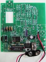
Figure 6. Completed HV section of the circuit
Attaching GM tube - Continuing Construction
Finish the construction of the circuit by adding the ICS-8 for the 555 timer and the ICS-14 for the LM339. Mount and solder all remaining resistors; R1 is a 1K resistor (color bands brown, black, red). R2, R4-R8, R12 & R19 are 10K resistors (color bands brown, black, orange). R3 & R11 are 1 Meg resistors (color bands brown, black, green). R13 is a 100K resistor (color bands brown, black, yellow). R15 & R21 are 330 ohm resistors (color bands orange, orange, brown). R16* is a 2.2 Meg resistor (color bands red, red, blue), and R20 is a 470 ohm resistor (color bands yellow, purple, brown).
Next mount and solder capacitors C1 & C2 (.1uF), C11 (.047uF) and C12 (.01uf). Mount and solder the two 1 Meg, 25-turn potentiometers (R10 & R14). Insert R14 in the correct position and bend flat prior to soldering. Now mount and solder the 5.1V zener diode (D2), the Audio switch, power jack, headphone jack and digital output jack. Mount and solder the speaker, transistors Q1, Q3 & Q4 (2N3904), 2-pin headers (P2 & P13) and LED (the longer of the LED terminals is positive (+) ) to the PCB. The LED should rise 3/8” from the PCB to the bottom of the LED. This distance will insure proper placement of the LED when the PCB is mounted inside the case. Mount and solder the bridge rectifier making sure to align the + terminal of the rectifier to the + terminal on the PCB. At this point your Geiger counter pc board should look like Figure 7.
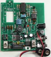
Figure 7 - Completed Circuit
*R16 is a 10 Meg resistor for LND712 GM Tube (GMT-01).
R16 is 2.2 Megs for GMT-02 GM Tube.
R16 is jumped with wire for external wand.
Attaching GM Tube
This pages hows how to connect two different style GM Tubes (the GMT-01 & the GMT-02).
The Geiger Muller tube has two leads. The GMT-02* is mounted on the bottom side of the case, see Figure 8 below. Use silicon glue to secure tube. The red wire from the GM tube is soldered to +GM tube lead on the PCB. The other wire is soldered to the (-) GM terminal on the PC board.
The Geiger Mueller tube is delicate and needs to be protected in an enclosure. Keep sufficient length of wire so that you can open and close the case.
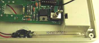
Figure 8. GMT-02 Geiger Muller Tube in Case
*If using the LND712 Geiger Muller tube (GMT-01), R16 should be a 10 Meg resistor. The jumper at P10 should be omitted, bringing the output voltage to 500 volts. This Geiger Muller tube also has two leads. It is mounted on the bottom side of the PCB. The wire connected to the metal sides of the tube is the negative terminal. This is soldered to the (-) GM terminal on the PC board. The center terminal of the GM tube has a removable solder lead. Remove the lead, solder 1.5” of wire to and. Reattach the lead to the center terminal of the GM tube. Take the opposite end of the wire and solder to the (+) GM terminal on the PC board.
The Geiger Mueller tube is delicate and needs to be protected in an enclosure. However the enclosure has a 1/2” hole that allows the front surface (mica window) of the GM tube to remain exposed. This way alpha particles can pass through the thin mica window and be detected.
After securing with a wire, as in Figure 9, a small amount of glue or epoxy can be dabbed on the wire tube assembly for added support.
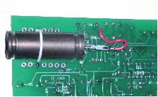
Figure 9 - Detail showing GMT-01 tube secured on PCB
*When attaching an external wand R16 should be jumped with a small piece of wire. The 10 mega-ohm re
sistor is is located inside the wand with the LND 712 tube. The connector for the wand, Jack-08, is soldered to the bottom of the PC board as shown in Figure 10.
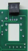
Figure 10 - Detail of Connector Mounted for External Wand
Test before Continuing General Construction
Before mounting the PCB inside the case, check to make sure the entire Geiger Counter circuit functions. Background radiation will cause the Geiger Counter to click about 12—22 times a minute depending on your location.
When you are satisfied that the circuit is working properly we can mount the circuit inside the case. Mount the PC board to the front of the case. The shafts of the two PC mounted switch and LED should fit into the pre-drilled holes. The PCB is held to the case front using the two nuts to the PC mounted switches.
Finish by placing the 9-volt battery cap into the battery compartment of the back case. Close the case and secure with case screws.
Installing /Changing Battery
To install or change battery open battery compartment on the back of the Geiger counter and install or replace battery, see Figure 11.
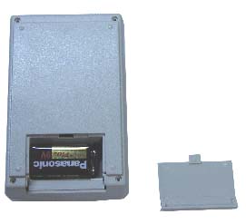
Figure 11
Features:
Head Phone
The headphone jack may be used for a headphones. When using the headphone jack for headphones the speaker is automatically cut-off.
Digital Output and Analog Meter
The digital output provides a TTL logic (+5V) pulse every time the Geiger counter detects radiation. This signal can easily be connected to a microcontroller or PC. The PC or microcontroller can then be used to create a digital Geiger counter, chart recorder or other recording instrument for nuclear experiments. The digital output may also be used to connect an analog meter to the unit. The analog meter is an accessory that plugs into the digital output and provides a visual indication of the approximate radiation level.
External Power Jack
The GCK-01 may be powered by either a 9-Volt battery or external power source with a 2.5mm jack.
Headphones, analog meters, external power supplies, and other accessories may be found on Images website http://www.imagesco.com
Radioactive Sources
Uranium ore is available from a number of sources including our online store.
The mantle in some Coleman lanterns are radioactive. Bring your Geiger counter to a local hardware store and check them out.
Uranium ore should also emit sufficient radiation to trigger the counter. It is available from a number of sources including our online store.
A more reliable source is to purchase a radioactive source. Small amounts of radioactive materials are available for sale encased in 1 inch diameter by ¼" thick plastic disks. The disks are available to the general public license exempt. This material outputs radiation in the micro-curie range and has been deemed by the Federal government as safe.
The cesium-137 is a good gamma ray source. The cesium 137 has a half-life of 30 years.
Check Out
Turn on the Geiger counter. If you have a radiation source bring the GM tube close to it. The radiation will cause the Geiger counter to start clicking. The LED will pulse with each click. Each click represents the detection of one of the radioactive rays; alpha, beat or gamma.
Background Radiation
Background radiation, from natural sources on earth and cosmic rays will cause the Geiger counter to click. In my corner of the world I have a background radiation that triggers the counter 12-20 times a minute.
Separating & Detecting Beta and Gamma
By placing shields of different materials in front of the GM tube we can filter out some radiation. For instance placing a paper shield in front of the GM tube will block all the Alpha radiation. The Geiger counter will now only detect beta and gamma radiations.
If we place a thin metal shield in front of the GM tube that would effective block the alpha and beta radiation, allowing
the detection of gamma radiation.
Parts List
The complete parts list and your choice of tube is available as the GCK-01 kit
(1) PCB-66
(2) 1K 1/4W Resistor - R1, R4
(7) 10K 1/4W Resistors - R2, R5, R6, R7, R8, R12, R19
(1)15K 1/4W Resistor - R9
(2) 1 Mega Ohm 1/4W Resistor - R3, R11
(1) 100K 1/4W Resistor - R13
(2) 330 Ohm 1/4W Resistors - R15, R21
(1) 10 Mega Ohm 1/4W Resistor - R16 (for GMT-01)
(1) 2.2 Meg Resistor – Alt R16 (for GMT-02)
(1) 5.6K 1/4W Resistor - R17
(1) 4.3K 1/4W Resistor - R18
(1) 470 Ohm 1/4W Resistor - R20
(1) 1 Meg 25-Turn Potentiometers - R14
(3) 0.1uF 50V Capacitors - C1, C2, C10
(3) 0.01uf 1KV Capacitors - C3, C4, C5
(1) 220uF 10V Capacitor - C6
(1) 22uF 50V Capacitor - C7
(2) 0.01uf 12V Capacitors - C8, C12
(1) 0.0047uf 100V Capacitor - C9
(1) 0.047uF Capacitor - C11
(1) 1N751 (5.1V Zener) Diode - D2
(1) Red Subminiature LED - D3
(2) 1N4007 Diodes - D4, D5
(1) 1N5271 (100V) Diode - D6
(2) 1N5281 (200V) Diodes - D7, D8
(1) 1N5817 Diode - D9
(1) 1N914/1N514 Diode - D10
(1) ICS-14
(1) LM339 - U1
(1) W01M - Bridge Rectifier - U2
(1) 7805 Voltage Regulator - U3
(1) ICS-16
(1) 4049 - U4
(1) ICS-8
(1) LM555 Timer - U5
(3)2N3904 Transistors - Q1, Q3, Q4
(1) IRF830 - Q2
(2) Jack-05
(3) SMH-02
(1) PJ-102A
(1) SPK-05B
(2) SW-07
(1) HVT-03
(1) BAT-01
(1) Jumper
(1) GM Tube
(1) Plastic Case (Sold separately)
GCK-01 Complete Geiger Counter Kit with GMT-02 (all components)
Components that are sold separately (click for more info or to purchase):
GM tube (GMT-01) $74.95 / GM tube (GMT-02) $44.95
Mini Step-up transformer $8.00
Radioactive Sources (click for more info or to purchase):
Uranium Ore (UR-01) $39.95
CS-137 Source $81.95 - $130.00 * Drop shipped from different location
Analog Meter
The Analog Digital Radiation Meter counts the pulse output of a standard analog Geiger counter to provide a visual readout of the CPS, approximate radiation level (imperial/metric) and analog radiation field strength meter.

Features:
- 7-12VDC or 5VDC power supply input
- Counts TTL pulses from Analog Geiger Counter
- Outputs Digital Counts Per Second (CPS) value
- Outputs radiation level (imperial / metric)
- LCD Backlight
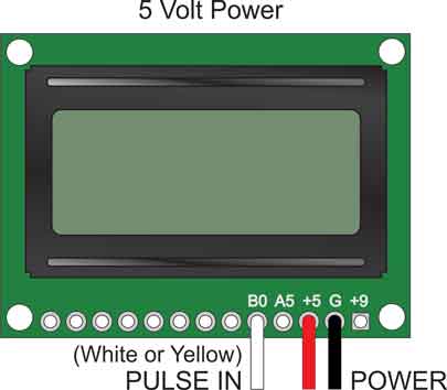
Images’ Analog Digital Meter allows you to add a digital display to your analog Geiger counter. The default display will provide readings in CPS and mR/hr. To switch the unit to display metric measurements (mSv/hr) a jumper is placed on the two-pin header on the back of the PCB.
The standard unit derives its power at either 5VDC, see image below for accurate wiring diagrams.
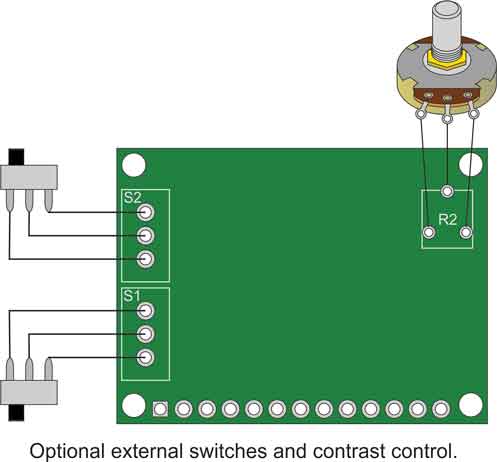
The meter features onboard switches that control power to the meter and backlight, as well as a control to adjust the contrast on the LCD. Additional options give you the ability to hardwire the unit so that the power to the meter and backlight remain on at all times that your geiger counter is on. In other words, "set it and forget it". You may also choose to add an external contrast control.
More Information: http://www.imagesco.com/geiger/analog-radiation-meter.html
Windows Geiger Counter Radiation Monitor Program
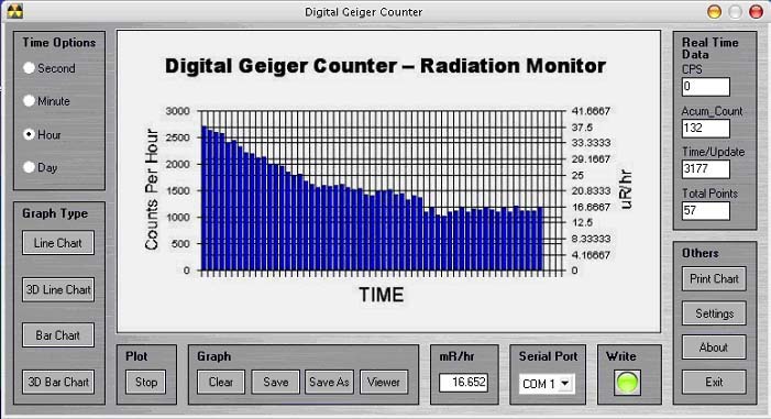
Figure 6 is a screen image of the Windows Geiger counter radiation program. This program is free and is available for download at the bottom of the page here.
You may download the NEWEST version of the software here. The program is fully functional for WIN7 and WIN 10.
The program gathers information it receives on one of its COM ports and displays the information on the PC screen. The information graphed is the Counts Per Second (CPS) from the geiger counter. The CPS scale is shown on the left side and equivalent radiation level in mR/hr is shown on the right side. The program automatically scales depending upon the CPS read. The graph continuously scrolls to the right with updated information. The graphs created with this program may be saved in disk and loaded for review later.
The amount of data that may be saved is limited by the memory in your system, or space available on your hard drive. But it is safe to say you could continue to graph for weeks.
To purchase the USB TTL Serial Cable click here.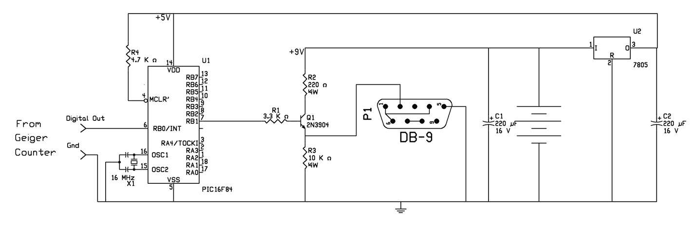
Circuit prototype is shown in Figure 8.
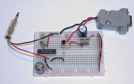
Figure 8. Picture of proto-typed PC Interface.