

Geiger Counter Charting Software is proprietary of Images SI, and is available free of charge http://www.imagesco.com/catalog/geiger/counter_accessories.html.
Geiger Counter Charting Software runs on Windows. Download the software installation file from Images SI website & install it on your PC. Connect the module to PC’s serial port via USB-TTL Cable adaptor. Module should be set to operate in DMAD / RS232 interface mode by setting switch B7 Up.
Make sure the program’s COM port is set to the correct COM port of the USB-TTL cable driver. Both the program and USB cabler counter COM ports must be the same for the program to begin graphing. The graphs generated by the program may be saved to disk and loaded for viewing and analysis later on. See screen image above.
Random Number Generator Function
B7 Switch Set = Random Number Generator:
| B7 | B6 | B5 | B4 | Range |
| Down | Down | Down | Down | 1-2 |
| Down | Down | Down | Up | 1-4 |
| Down | Down | Up | Up | 1-8 |
| Down | Down | Up | Down | 1-16 |
| Down | Up | Up | Down | 1-32 |
| Down | Up | Up | Up | 1-64 |
| Down | Up | Down | Up | 1-128 |
When B7 switch is in its Down position it is set and the module will function as Random Number Generator. Switch B7 is only checked when module is turned on, so switch setting should be changed only when module is off. Changing the switch set-ting while module is pow-ered will not change func-tionality of module.
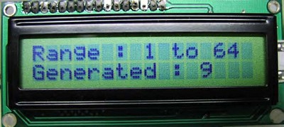
Random Number Generator functionality generates Random Numbers true in nature. For this purpose, the module can be used with either of Analog or Digital Geiger Counters. The module plugs into Digital out or Headphone jack as before. Range of random number generated is selected by combination of switch settings B6, B5, B4.
The serial output transmitts the random number generated. The information is transmitted as a single bytes. This data may used by various PC programs that require true random numbers.
Writing Your Own Software to Communicate with the Adapter
You can write your own software to communicate with this module. Serial data is sent out as a two byte number (most significant byte first) with the following specifications: 9600 Baud, Inverted, 8 data bits, no parity and one stop bit.