
Construction Of DMAD Module
Figure 1 below shows the schematics of DMAD Geiger counter expansion module.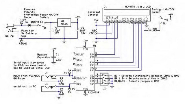
The circuit uses a pre-programmed 16F88 microcontroller and a standard 16 x 2 LCD display. Module derives itspower from either an 9V external battery, or optional 6VDC power supply. Power is regulated on board to 5V. Input to module comes via 3.5 mm jack J1. Module features TTL serial out port via a two pin header or 3.5 mm jack J2. Either of which can be used for an interface. The 3.5mm jack is used with USB-TTL serial cable. The back of Universal Expansion Module has a Power switch, LCD backlight switch, Contrast control, Selection switches, see Figure 3.
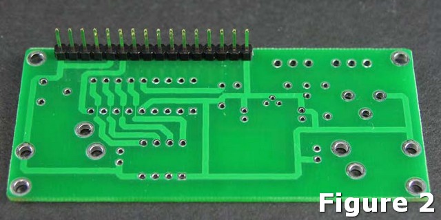
Begin by mounting and soldering the 16-pin header on the bottom of the board (the side with no silkscreen) as shown above in figure 2. Next, on the top of the board (silkscreen side), mount and solder the ICS-16 for the PIC16F88 microcontroller to the board, making sure the notch on the socket is aligned with the silkscreen. Now, mount and solder the two slide switches marked S1 & S2, followed by power jack P3. Next, mount and solder R1 the 33 ohm resistor. Next mount the 1N5817 diode D2 making sure to align the stripe on the diode with the strip on the silkscreen. Q1 is the regulator. When mounting the regulator, be sure the flat side is oriented with the flat side of the silkscreen. Next mount the three 2-pin headers in the top two sets of holes marked P1,P2 then P4,P6 and P5,P7. These 2-pin headers provide an alternate method of connecting to the board to supply power, digital input, and serial output respectively.Now, mount C1, the 0.1uf capacitor and the two 10uf capacitors marked C2 & C3. When mounting these capacitors be sure the longer lead is oriented to the hole marked positive.
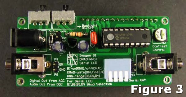
Mount and solder the Digital Input jack J1 and serial Output jack J2. Followed by the 20K pot in the spot marked R2, Contrast Control. Mount and solder the 4-position switch in U2. Next, mount and solder 18 Pin socket U1 to the PC board.
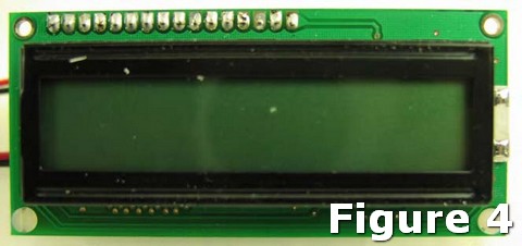
Next mount and solder the LCD module to the 16-pin header. Figure 4 is a photo of the top of the completed circuit.