
RS-232 Adapter for used with older PC's with a serial DB-9 Connector:
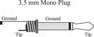
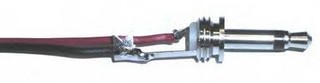
Begin with wiring the 3.5mm jack. The shorter lead inside the jack is the positive, the longer is the negative (ground). To the positive (tip) terminal solder a red wire, to the ground solder a black wire (See Figure 5 & 6). Once the wires are soldered to the plug, thread the wires through the body of the jack and screw the body down on the plug.
 |
 |
| Figure 5 | Figure 6 |
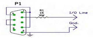
To utilize the RS-232 you need to connect a DB9 connector to the wires off the 3.5mm (1/8”) jack. The DB-9 female connector is wired as shown in figures 7 and 8. Once the internal DB9 connections are soldered.
 |
 |
| Figure 7 | Figure 8 |
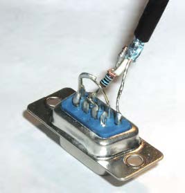
Soldered the red wire from the jack to the I/O line of the DB9 connector. Don’t forget to wire in the 1K resistor. Next the and ground wires from the DB9 connector and 3.5 mm plug are connected together Encase DB-9 connector in DB-9 connector hood. The resulting cable will resemble figure 9.
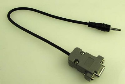 |
| Figure 9 |
To use this cable plug the 3.5 mm (1/8”) jack into the serial out socket (J2), see figure 10.
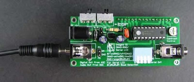 |
| Figure 10 |
Connect the DB9 connector to an open RS-232 port (COM port) on your computer.
Alternatively use can also use a USB port, by connecting a USB-TTL Serial cable to module's serial port output to an open USB port of your computer.
Either option provides a serial link interfaced with PC for Graphing & Logging Radiation Levels using Images SI Graphing Software available for free download on Images SI website.