
You can write your own software to communicate with the RS-232 adapter. The RS-232 serial data is sent out as a two byte number (most significant byte first) with the following specifications: 9600 Baud, Inverted, 8 data bits, no parity and one stop bit.
You may also use the USB adapter to communicate to the software using the standard COM port. The USB to Serial Adapter sets the USB communication to COM port 3.
Construction
The components are mounted on the silkscreen side of the printed circuit board (PCB), see figure 3.
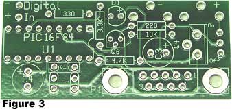
Begin construction by mounting and soldering all the 1/4 watt resistors. 330 ohm, (color bands orange, orange, brown) 3.3K (color bands orange, orange, red), 4.7K (color bands yellow, purple, red), 220 ohm (color bands red, red, brown), 10K (color bands brown, black, orange). Capacitors C3 and C4 are electrolytic capacitors whose valve may range between 100-300 uf. Mount and solder capacitors C3 and C4. Next mount and solder 18 pin socket for the IC 16F84 (or 16F628). Then mount and solder the 16MHz crystal marked XTAL on the printed circuit board (pcb). Then capacitors C1 and C2 (22 pF).
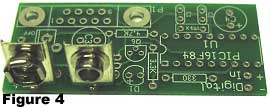
Mount the right angle DB-9 connector on the pcb. Don't force the connector into the pc board. Gently rock the Figure 4connector back and forth, making sure the pins line up with the holes, and press down. Solder into position. Mount and solder the (+) and (-) battery terminals onto the pc board. Make sure you are soldering the correct terminal, see figure 4.