
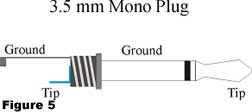
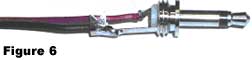
Solder a 5-1/2" wire to the 3.5 mm jack, see figure 5. To the positive (tip) terminal solder a red wire, to the ground solder a black wire. Once the wires are soldered to the plug, see figure 6, thread the wires through the body of the jack and screw the body down on the plug.
Solder the red wire from the 3.5 mm jack to the Digital In on the pc board and the ground wire to the ground next to the Digital In.
Next mount and solder the 7805 voltage regulator, Q6 (2N3904 or 2N2222 Transistor), orientate the transistor to match the silkscreen outline in the pcb. Mount and solder D1 red LED. The longer terminal on the LED is the positive terminal. Orientate, mount and solder the red LED D1. Next mount the right angle on-off pc mounted switch.
Finish construction by mounting the pre-programmed PIC 16F84 into the 18-pin socket.