SELECTING THE RIGHT CORE FOR THE OUTPUT
Winding inductors and transformers is easy and fun, and puts you in charge of at least one aspect of electronics design. And yes, it can be frustrating at times! Many cores and styles of cores were tested with this circuit and I have a few recommendations. The best performance is achieved with a toroidal core. Toroids have many advantages over other core shapes - continuous flux path, low flux leakage and thus lower leakage inductance. Toroids are also available in a wide range of sizes, and they are a cinch to wind.
The best toroidal core to use is a ferrite with a very large AL value, 4000nH/N2 or greater, rated for operation into the MHz region. The AL value, also known as the “inductance factor” is given by the manufacturer and defines the inductance of an “unbroken core” in nanoHenries-per-turn-squared, taking into consideration the recommended winding method prescribed by the manufacturer. With the AL value the formula for calculating inductance of an inductor is made very simple:
L(nH) = (AL)(N2)
N is simply the number of turns wound on the core.
You might be able to find a usable core in old equipment but without a reliable inductance meter capable of measuring inductance from nanohenries to millihenries your results will be problematic. Building a PIC based Inductance/Capacitance meter is not hard and will make your experiments with magnetic materials a lot easier to perform. You can even use the meter to calculate the AL value of an unknown core as was done with the core used in this project.
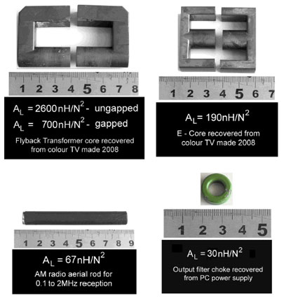
Below I give the measured AL values of a few cores that I tried. It is noteworthy that none of these produced a clean output. Some produced highly distorted outputs containing significant high frequency harmonics (>2 MHz) – EMI problems. Others caused the MOSFETs to run hot.
SOME CORES TESTED AND REJECTED - (ruler = centimeters)
There are many suppliers of toroidal cores that should be applicable to this project. Two obvious ones are Ferroxcube and Epcos. I would aim for a core with an outer diameter in the 30mm to 35mm region, and an inner diameter of about 20mm. This core size will make winding the transformer a lot easier, especially with thick wire.
Avoid powdered iron cores – totally! They are designed for DC choke applications and have very low AL values, and they exhibit significant losses with increasing frequency. These toroids are often the green coloured ones you will see in the input/output stage of a PC power supply or other style switching power supply.
WINDING THE TOROIDAL INDUCTOR
Before winding the enameled copper wire on the core place a layer of insulation tape over the core. This protects the windings from damage during the winding process. A strip of insulating tape 12cm long by about 0.8cm wide should suffice - just cut-off the excess. As the inductor will be handling currents of about 2A continuous, perhaps a little more, I used 18-gauge (ca. 1mm thick) enameled copper wire.
Take three 1 meter lengths of 18-gauge enameled copper wire (magnet wire) and secure the ends together with a small strip of electrical tape or shrink wrap as shown in the diagram below. Thread the three strands of wire through the core hole, leaving enough wire to be used later as suitable connections. Now wind 15 turns of the three stranded magnet wire onto the toroidal core – wind either left or right going – it matters not. The style and manner of winding should be obvious from the photos above showing the inductor built for the prototype unit. This style of winding is called trifilar winding. If you are careful and patient you will have 15 groups of three parallel wires wound tightly and neatly on the core. There will be 45 loops of wire on the toroid, 15 for each winding. Of course evenly spaced around the core as shown in the photo above!
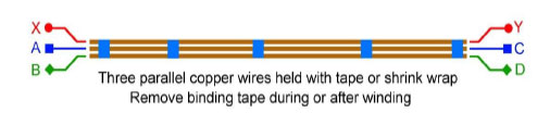
Secure the ends of each group of windings with electrical tape as shown in the photo. You might find it advantageous to add tape along the length to make manipulating the three parallel wires wire less cumbersome. Leave about 5cm of wire for the leads. Scrape the enamel coating from the ends of the wires and tin the ends. You may need to re-identify each winding using a continuity meter or a multimeter.
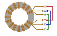
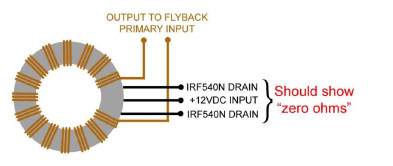
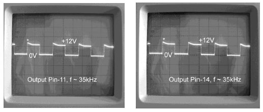
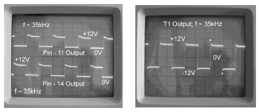
All that remains is interconnecting the windings. Connect “B” and “C” together. This wire is connected to the +12V power rail and “XY” is the output pair and “AD” the drain pair, but a note of caution. Wiring mistakes do happen. The toroidal inductor must be connected correctly to get a relatively clean ±12V square wave output to feed to the primary of a high ratio step-up transformer or flyback. The output of a properly connected inductor looks like this on an oscilloscope.
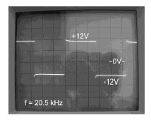
If you do not see such a trace you have probably attached the “OUTPUT PAIR” of the inductor to the MOSFET DRAINS. If so, just exchange the windings – there are only two real choices here.
In the absence of a scope, a multimeter should indicate which pairs of windings are the correct ones. They will be the ones that show “zero ohms” on the multimeter or very, very low ohms if you have a fancy multimeter. See the diagram below.