
A Few more Notes on the Output Inductors
A simplistic definition of “magnetizing current” is the current that flows in the primary winding when no load is attached to the secondary. From basic high school physics we know that the voltage across an ideal inductor is given by:
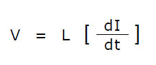
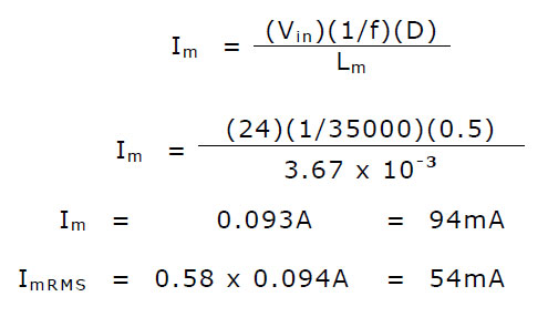
Here we can say that V is our input voltage Vin, I is the peak magnetizing current Im and L the magnetizing inductance Lm. So rearranging and redefining gives the magnetizing current as:
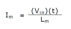
“t” (dt) the time the current is on, is simply the duty cycle “D” divided the switching frequency f:
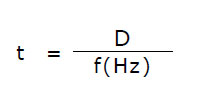
In reality the current through the inductor takes the form of a triangular wave so a more meaningful result is its RMS value, and for a triangle wave this is given by:
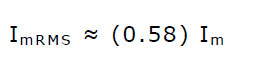
For example, consider the case of the toroidal inductor used in this prototype subjected to a ±12V square wave, operating at 35kHz with a 50:50 duty cycle (D = 0.5). The input winding has a measured inductance of 3.67mH.
From this we can see that the magnetizing current decreases with increasing inductance. As the switching frequency approaches that of a DC current source (very low f), the magnetizing current increases very rapidly. Although leakage inductance is likely to increase with increasing inductance the choice of a toroid should ensure that leakage inductance is much lower than with other core shapes. Without a load attached to the output, the inductor windings should remain cool, and so too the MOSFETs. This has been verified over a switching frequency of 5 kHz to 110 kHz.
Just a brief note on wire size used! Normally one would also take into account the “skin effect”, and for copper conductors the penetration depth of an AC current at a given frequency can be calculated by the formula:
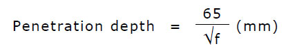
And here f is the switching frequency in Hz. Because this design covers switching frequencies as low as 5000 Hz to about 90,000 Hz depending on the transformer driven, we use what is readily available and practical, and in this case 1 mm diameter enameled copper wire was a reasonable choice. Litz wire, if available, would have also been a very good choice too.