
UNIT DURING FINAL TESTING
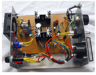
Above is a photo of the top of the unit showing the PCB and some of the other components. The cables were secured with cable ties for safety and neatness. Next to the fan is the output inductor discussed in the section entitled “Some notes on the output inductor.” When operating at 3A output or less the inductor barely becomes warm, but for higher current outputs to drive 100W or 200W HV step up transformers its placement next to the fan is essential.
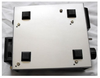
Above is the bottom of the unit showing feet and screws used to secure the PCB to the case. All screws use star washers for secure attachment.
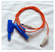
To connect the unit to the HV step up transformer during the experimentation phase I used banana plugs and these are superb. Reliable and easy to use. Very quick installation. The wire is from an old PC power supply and is rated at 15A. It was soldered to both the banana plug and alligator clip.
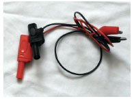
To connect the unit to the power supply I used banana plugs and these are superb. Reliable and easy to use. Very quick installation. The wire is from an old PC power supply and is rated at 15A. It was soldered to both the banana plug and alligator clip.
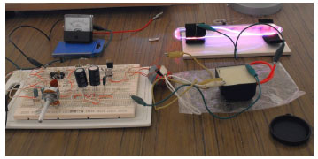
And how it all began as a bread-boarded unit on the kitchen table