
UNIT DURING FINAL TESTING
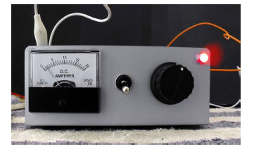
Above is a photo of the completed unit during final testing. Before placing on any panel artwork I run the unit for 72 hours and then disassemble it. I look for damage or any electrical faults. When satisfied I place the artwork on the appropriate metal panels, reassemble the unit, and run it for another 12 hours.
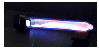
The 20cm Plasma tube energized by the unit above and during final testing.
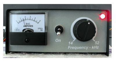
Above is a photo of a fully functional unit. The front panel contains an Amp meter (5A), switch and pot for varying the frequency along with a nice LED to indicate power. The original 20A meter was replaced. Until I can get or make some HV transformers with greater than 100W power rating I will limit output to about 2A maximum.
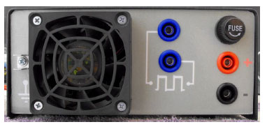
The rear of the unit shows the earth tab, 12V PC fan and banana sockets and fuse. The fan and fuse are not essential if you are driving transformers with less than 3A. However both the fan and fuse become very handy when you start driving 100W or 200W HV step-up transformers. The fuse is rated at 5A slow blow. The fan is from an old AMD CPU chip.
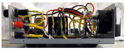
Above is a photo of the side view of the instrument. I used spade connectors for the power, switch, fuse, earth and amp meter connections. The PCB was fitted with spade connectors too as detailed in the section entitled Making the PCB. The connecting wires were salvaged from a discarded PC power supply and are rated at 15A. They were soldered to the spade connectors. The PCB uses 10mm stand-offs and beneath the PCB was placed a sheet of plastic to prevent accidental short circuits with the metal case.
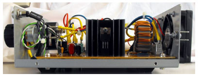
The above photo shows the other side of the instrument. The pot and led use connectors salvaged from an old PC. During testing I did not solder the Mosfets to the board to enable quick and easy replacement should they blow. However I saw no problems or difference in performance and decided to leave them in the sockets. The heatsinks are also attached to the PCB with screws to allow for easy replacement should the need ever arise. Again the heatsinks become very handy when driving 100W or greater HV step up transformers.