
HV TRANSFORMERS USED IN THE WORK
Two high ratio step-up transformers were used in this work; one labeled Excitron and the other labeled Images HVT-01. The one that gave the best overall performance was labeled Excitron. It has two independent primaries and one secondary like the HVT-01, but the primary pin assignments differ as discussed below.
It is not a large transformer as the photo below shows. It is rated at 50 watts, so with a 24V input, the current should not exceed about 2A. It is a very reliable transformer, but like all electronic devices it will be destroyed, and very quickly, if the specifications are exceeded. This is based on personal experience with these transformers. I have destroyed two and in each case it is the secondary winding that fails.
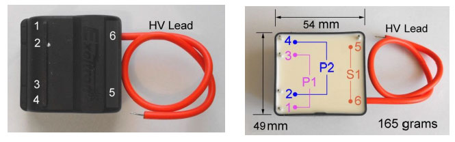
Above are two photos of the Excitron HV transformer. On the left is a photo of the top showing pin assignments and on the left a photo detailing the primary and secondary coil set-up.
To achieve a much more “energetic” output a 100 watt or perhaps even a 200 watt transformer is needed. The easy solution is to obtain a flyback core and wind your own transformer.
Some Measured Data for Excitron Transformers
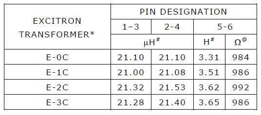
* My designation to identify individual transformers.

# Inductance ca. 1mH or more, measured with Digitech QM1548 Digital DMM.
@ Resistance measured with a Digitech QM1548 Digital DMM.
Plasma Driver High Ratio Step Up Transformer
INSIDE A HVT-01 HIGH RATIO STEP-UP TRANSFORMER
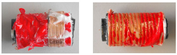
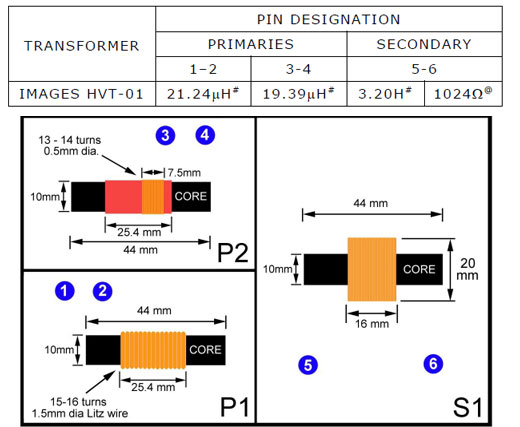
Above are two photos of the primary windings of a dismantled HVT-01 transformer – one that died during experimentation for the greater good! As can be seen from the photos there are two independent primary windings designated P1 and P2. P1, (15-16 turns) shown on the right, comprising Pins 1 & 2 is wound with Litz wire (1.5mm diameter), and can presumably handle more current than P2. P2 (13-14 turns) shown on the left comprising Pins 3 & 4 is wound with 0.5mm diameter enameled copper wire.
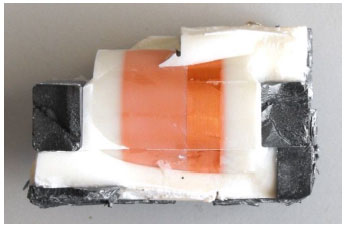
Above is a photo of the secondary of the dismantled HVT-01 Transformer. It is wound with very fine wire, 0.05mm diameter, perhaps even finer, using the multi-layer style of winding. It is difficult to say if these transformers contain true gapped “flyback” cores. They contain no shim and the two halves of the core are secured with a small quantity of glue. In effect two “C” cores stuck together.
SOME MEASURED DATA FOR A HVT-01 TRANSFORMER

#Inductance ca. 1mH or more, measured with Digitech QM1548 Digital DMM.
@ Resistance measured with a Digitech QM1548 Digital DMM.
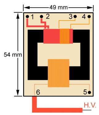
Above is a diagrammatic representation of the Images HVT-01 showing the spatial relationship between all primary windings, and the secondary winding. The core fits snugly into the housing, but is also held in place with a suitable support not shown in the diagram. The pins are part of the support and the windings are soldered to the pins and the core rests on the support. The whole transformer is encapsulated in epoxy.
What Makes Flybacks Fly
Many electronics enthusiasts often confuse a flyback with a standard power transformer or even a high ratio step-up transformer. A “flyback” is not a transformer even though it may look like one. Your common “garden variety” power transformer is a power transfer device where input and output windings conduct simultaneously, and power is transferred from the primary coil to the secondary coil continuously. In simple terms a flyback is an energy reservoir - filled when the switching device is on, and emptied when the switching device is off. In this application the switching device is a MOSFET. A flyback is therefore an energy-in, energy-out power transfer device where the input and output windings do not conduct current simultaneously. So think of a flyback as two independent inductors which share the same core.