
Notes on HV Voltage Power and Resonance
The table and graph below show output current drawn as a function of frequency for energizing a 20cm long low pressure Plasma tube. The graph can also be viewed as one of output voltage and output power, and it is clear that both reach a maximum with an applied switching voltage of ±12V operating at a resonant frequency of 29.2kHz. The best plasma discharge for this tube in terms of appealing light display, occurred close to resonance, but the transformer could not operate at such high current loads for more than a minute without sustaining permanent damage to the secondary winding. A continuous current of 2A is the maximum limit for these Excitron transformers when driving a 20cm long Plasma tube, unless fan cooled. The display is still very attractive in my opinion, as the photo below shows.
Table.1: Frequency vs Current for an Excitron Transformer*
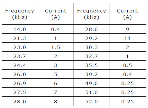
To avoid damage to the Excitron transformer the frequency meter was placed next to the Panel meter of the Flyback driver unit and the change in current versus frequency recorded with a digital camera. Results were acquired directly from the footage and scan time was 8 seconds.
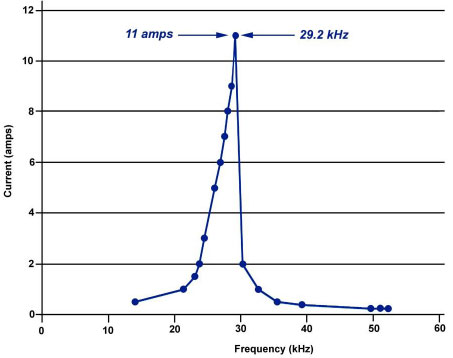
Excel graph showing the Resonance curve
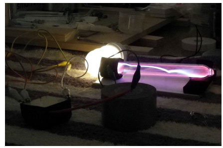
Plasma tube and fluorescent house light energized at about 23.0kHz/1.5A. Only the Plasma tube is connected to the Excitron HV output via a small piece of conductive foam. The house light is energized just by being in the vicinity of the Plasma tube. Note that the best lighting effects (in my opinion) occur on the left-hand side (<29kHz) of the resonance curve.
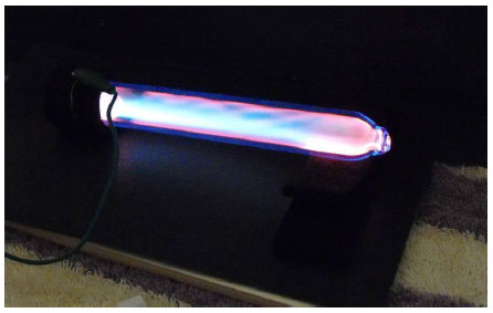
Even at the lowest setting of 14.3kHz/0.4A you can still get an attractive glow discharge from the Plasma tube.
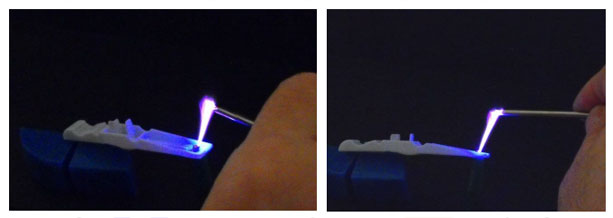
Connecting the output of the Excitron transformer to an alligator clip one can draw some very intense “sparks” (21.3kHz/1A), with the business end of a phillips head screw driver. The sparks shown are about 3cm long and very intense. Longer ones (~5 cm) can be drawn but it is difficult to keep them stable to photograph. At higher currents, especially near resonance, much longer sparks can be anticipated. Regrettably arcing within the secondary is very probable at these currents.
The main drawback with the Excitron is the potting. This restricts external cooling and thus limits the continuous current to about 2A. An un-potted core could be immersed in mineral oil that would not only act as a coolant, but also reduce internal arcing within the secondary windings.
SUGGESTED READING
SG3525AN Data Sheet;IRF540N Data Sheet
International Rectifier, AN-936; The Do’s and Don’ts of Using MOS-Gated Transistors;
International Rectifier; AN-937 Gate Drive Characteristics and Requirements
FERROXCUBE; Soft Ferrites and Accessories DATA Handbook 2013
EPCOS: Ferrites and Accessories Data Book 2013
Construction Project: “High Accuracy Digital LC meter” by Jim Rowe in Everyday Practical Electronics Magazine, March, 2010, pp 10-17.