Construction
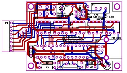
Start kit construction by identifying the component side of the printed circuit board (PCB). The component side has the white line drawings of the resistors, transistors, diodes, IC's and USB connector. All components are mounted on the component side, EXCEPT FOR THE 8 PIN FEMALE HEADER.
In general after soldering a component to the board, clip away any excess wire from the underside of the printed circuit board. Follow the
sequence for mounting the components as outlined.
Start by mounting and soldering the 330 ohm resistors (color bands orange, orange, brown, gold) labeled R1 & R3. Next mount R2 the 4.7K resistor (color bands yellow, purple, red, gold). Mount the red LED labeled D1, and green LED (D2) on the board. The positive lead of the LED is the longer lead. The positive lead of the LED is mounted in the + label.
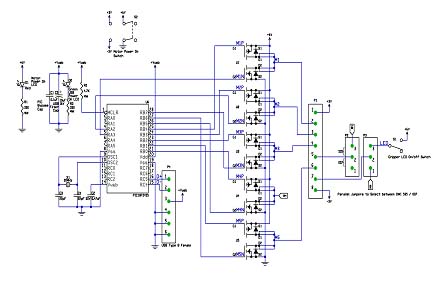
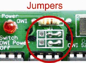
Next mount the 8 pin sockets (U1-5) and the 28 pin socket for U1, align indentation on sockets to match silkscreen. Mount and solder the USB connector. Mount the On-Off (S2) switch and the small slide switch (S1). Mount and solder C1 (0.1 uF) and C3 & C4 (22 pF) by the crystal and C2 (.47 uf) capacitors. Mount and solder C5 (10 uF 16V),keeping the positive terminal of the capacitor orientated as shown in the drawing above. Next mount and solder the 20 Mhz crystal. Next take two small pieces of wire and solder them into position as shown in the Jumper image below.
Finish the project by mounting and soldering the 8 pin female header to the underside of the board. Mount the preprogram 18F2455 chip into the 28 pin socket and mount the five MOSFET P605 into the 8 pin sockets making sure to align indentation on chips with socket indentation and silkscreen outline.