
In the Beginning there is Binary
The term binary means "based on two" as in two numbers, 0 and 1. It's also like an electrical switch that has two values on (1) and off (0).
The term bit is an acronym that stands for the term Binary digit. A bit or binary digit can have two values, either 0 or 1. A byte is a digital expression (number) containing 8 bits.
Binary is important to computers and microcontrollers. The bit values of (0) and (1) are the only things a computer can read. Actually the computer or microcontroller can't really read, but it can sense voltage values. So a bit that is on (1), is represented by a positive voltage. Consequentially a bit (0) is off (0) and is represented as no voltage.
A single bit by itself is of little value, but start putting them together to make Bytes (8-bits), Words( 16-bits) ((32 bits) (64 bits) (128) and so on) and we can make the computers perform mathematics, create word processors, spreadsheets , create a cyberspace (internet) etc. All these amazing things based on a bit.
Reading and Writing
To read or write to microcontroller pin (I/O line) or a port register requires understanding a little binary. When we read the staus of an I/O line or pin on our microcontroller we are seeing if there is a binary 1 or binary 0 present of the line. When we write to any pin or I/O line we are outputting either a binary 1 or binary 0. When reading or writing to a port, we can influence all the pins or I/O lines available on that port at one time. While we may typically use standard decimal numbers when writing to or reading a port status, it is the binary equivalent of that number that the microcontroller uses. Therefore when writing to a port you can use decimal (or hexadecimal) numbers but only if you can understand the binary number equivalen that the PIC Microcontroller uses.
Setting Individual Pins to be either Inputs or Output Pins
PBP compiler has commands that allows you to read and write to indivial pins or complete ports at a time. The command INPUT will cause the identified pin (following the command) an input pin. So for example INPUT PORTA.0 will make PORTA, pin 0 an input. To turn this pin into an output you can use the PBP command OUTPUT. The command OUTPUT will cause the identified pin (following the command) an output pin. So for example OUTPUT PORTA.0 will make PORTA, pin 0 an output. The advantange of using these commands is that it also sets the Data Direction Register (DDR) or TRISA at the same time. See explaination and access of TRIS registers below. The disadvantage is that in program execution time is slower than if you set the TRISA yourself. Typically the program execution time is so quick, the slight decrease in time is not noticable.
What are the PORTA, PORTB, TRISA and TRISB Registers?
The 16F88 has two 8-bit bi-directional ports; PortA and PortB. Each bit of these ports correspond to a PIN on the 16F88 microcontroller. Each of these Ports has a Data Direction Register TRISA for PortA and TRISB for PortB. The TRIS bit determines whether the corresponding bit on the port is either an input or output pin. Setting the TRISA bit (= 1) will make the corresponding PORTA pin an input. Clearing a TRISA bit (= 0) will make the corresponding PORTA pin an output.
Accessing the Ports and Registers
The 16F88 uses 8-bit registers for PORTA, PORTB, TRISA and TRISB registers, so we only need to concern ourselves with small 8 bit numbers and their decimal equivalent right now. Accessing a port or register on the PIC microcontroller allows you to set eight I/O lines or pins at once. Remember an 8 bit number is called a byte. An 8-bit number can represent any decimal value between 0 and 255. When we write a decimal number into a register, the PIC microcontroller can only see the binary equivalent of that decimal number (byte) we wrote to the register. For us to understand what's happening inside the register we need to be able to look at the binary equivalents of the decimal (byte) number also. Once we can do this, our ability to effectively and elegantly program the PIC microcontrollers is enhanced.
Examine the binary number table below, it shows all the decimal and binary number equivalents for numbers 0 through 32. Using this information, the binary numbers from 32 to 255 can be extrapolated.
Each decimal number on the left side of the equal sign has its binary equivalent on the right side. So where we see a decimal number, the microcontroller will see the same number as a series of eight bits. (bits -- eight bits to a byte)
Binary Number Table
0 = 00000000
1 = 00000001
2 = 00000010
3 = 00000011
4 = 00000100
5 = 00000101
6 = 00000110
7 = 00000111
8 = 00001000
9 = 00001001
10 = 00001010
11 = 00001011
12 = 00001100
13 = 00001101
14 = 00001110
15 = 00001111
16 = 00010000
17 = 00010001
18 = 00010010
19 = 00010011
20 = 00010100
21 = 00010101
22 = 00010110
23 = 00010111
24 = 00011000
25 = 00011001
26 = 00011010
27 = 00011011
28 = 00011100
29 = 00011101
30 = 00011110
31 = 00011111
32 = 00100000
.
.
.
64 = 01000000
.
.
.
128 = 10000000
.
.
.
255 = 11111111
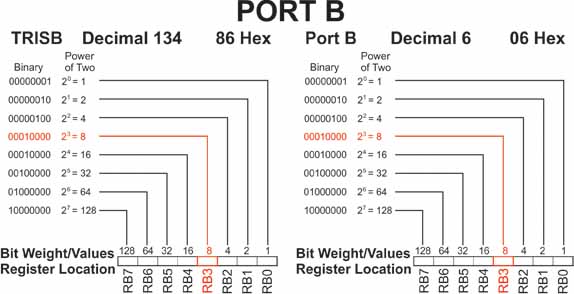
Figure 1 (below) shows the relationship between a binary number and the two PIC microcontroller registers that control Port-B. Notice each register has eight open positions. This register can hold an 8-bit (1 byte) number.
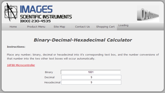
Binary-Decimal-Hexadecimal Calculator
The following link brings you to a binary-decimal-calculator page. Binary-Decimal-Hexadecimal Calculator Page. Place any number; binary, decimal or hexadecimal into it's corresponding text box, and the number conversions of that number into the two other text boxes will occur automatically.
Counting in Binary
To reinforce the binary number system lets write a program that counts from 1 to 16 and displays the decimal number in binary using four LED's. If we look at figure 1 we see RB3 is highlighted in red. It is highlighted in red because that pin I/O line has been assigned to the LCD display. Therefore we ought to leave that pin/line alone. Our counting program from 1 to 16 would typically use the pins I/O lines RB0 to RB3. Since we can not use RB3, what we will do in this program is shift the number four places to the left to RB4 to RB7 and display the LED's
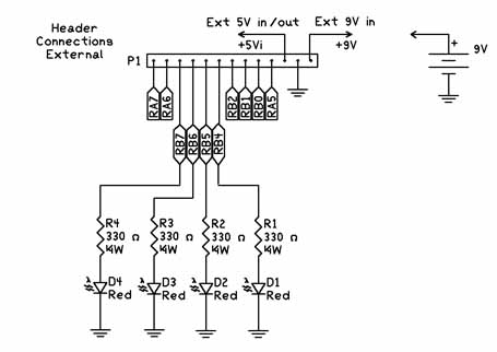
Below is the schematic for the Binary counting program.
'Binary Counting Program
| osccon = %01110100 | 'Set-up internal oscillator at 8 Mhz | |
| define OSC 8 | 'define the oscillator frequency | |
| ANSEL = %01100000 | 'Set RA0-RA4 as digital I/O for LCD leave RA5 and RA6 A/D | |
| trisb = 0 | ' Set Port B to outputs | |
| pause 1000 | 'Initalize time for LCD | |
| j var byte | 'Create variable j | |
| i var byte | 'Create variable i | |
| start: | 'Label for start of program | |
| For J = 0 to 15 | 'Start counting loop | |
| i = j << 4 | 'shift number 4 places to right | |
| portb = i | 'display binary number using LEDs on RB4 to RB7 | |
| pause 500 | 'Delay to give human time to see LED binary number | |
| next j | 'next number | |
| goto start | 'Start from the beginning again |
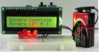
Our Binary counting program works pretty well. Notice that the "j" variable is between 0 and 15. This is because computers start counting at zero, while we humans starting counting at one. One thing missing from out program is using the LCD Display to provide information on program executuion. With a few more lines we can add an LCD routine that shows the decimal equivalent of the binary number shown on the LEDs. If the program runs too fast for you increase the Pause 500 line to Pause 1000.
'Binary Counting Program with LCD
| osccon = %01110100 | 'Set-up internal oscillator at 8 Mhz | |
| define OSC 8 | 'define the oscillator frequency | |
| ANSEL = %01100000 | 'Set RA0-RA4 as digital I/O for LCD leave RA5 and RA6 A/D | |
| trisb = 0 | ' Set Port B to outputs | |
| pause 1000 | 'Initalize time for LCD | |
| LCDOUT 254,1, "Binary Counting" | 'Print on LCD line 1 | |
| j var byte | 'Create variable j | |
| i var byte | 'Create variable i | |
| start: | 'Label for start of program | |
| For J = 0 to 15 | 'Start counting loop | |
| LCDOUT 254,192, " " | 'Clear printing on LCD line 2 | |
| LCDOUT 254,192, "Binary LED # ", #j | 'Print on LCD line 2 | |
| i = j << 4 | 'shift number 4 places to right | |
| portb = i | 'display binary number using LEDs on RB4 to RB7 | |
| pause 500 | 'Delay to give human time to see LED binary number | |
| next j | 'next number | |
| goto start | 'Start from the beginning again |