
The ability of our microcontroller to read the electrical status of its pin(s) allows the microcontroller to see the outside world. The line (pin) status may represent a switch, sensor, or electrical information from another circuit or computer. And as we'll see later can read an analog voltage on a pin using the 16F88 microcontroller's built in Analog/Digital (A/D) converter.
If a +5 TTL voltage is present on a pin (I/O) line and we looked at the line we would get a binary "1". If zero voltage or ground is present on a pin (I/O) line and we looked at the line we would get a binary "0". The figure belows shows two simple switch configurations that can place either a binary "1" at a pin (switch A) or a binary "0" (switch B). The status of the line reverses if one presses down on the momentary switch.
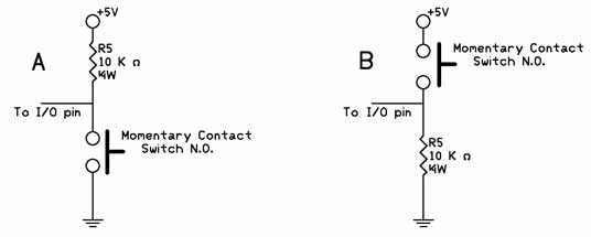
Lets take another look at the switch schematic in figure 4 before we start using the switch in a program to visualize how the switches affect the I/O pin electrically.
The switch labeled "A" connects the I/O pin to a +5V power supply through a 10,000 ohm resistor. With the switch open, the electrical status of the I/O pin is kept high (binary 1). When the switch is closed, the I/O pin connects to ground, and the status of the I/O pin is brought low (binary 0).
The switch labeled "B" has an electrical function opposite the switch labeled A. In this case, when the switch open the I/O pin is connected to ground keeping the I/O pin low (binary 0). When the switch is close the I/O pin is brought high (binary 1).
In place of a switch, we can substitute an electrical signal, high or low, that can also be read usig the Button command.
Typically checking the switch status is accomplished inside a program loop, where the program is looking for a change of state (switch closure). When the state of the I/O pin (line) matches the state defined in the commandr, the program execution jumps out of the loop to the "Label" portion of the program.
We can use standard PBP commands to read the status. Let's say our switches are connect to RB0. In the case of the A switch, the line is normally high (binary 1), so to detect a switch press we want to see a binary "0".
lp:
if portb.0 = 0 goto routine2
goto lp
routine2:
In the program snippet above, the line "if portb.0 = 0 then goto routine2" checks the status of pin RB.0. In the case where RB0 = 1 the routine jumps back to start and keeps re-checking the statud until it changes. The program can be easily modified to check for a binary "1", for the use with switch B, see below.
lp:
if portb.0 = 1 goto routine2
goto lp
routine2:
Reading an Input Line
Now its time to use a momentary contact button to our application. By adding a switch we can have the program stop or start at the press of a button. The image below is a minature momentary contact push button switch Normally Open (N.O.)
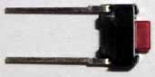
This particular momentary contact switch has terminals that are for soldering directly to a pc board, but also plug right into our solderless bread board making connection into our circuit easy.
For this example we will have the program stop counting while the switch is pressed and resume where it left off when the switch is released. The first thing we need to do is add our switch to the circuit. The schematic follows.
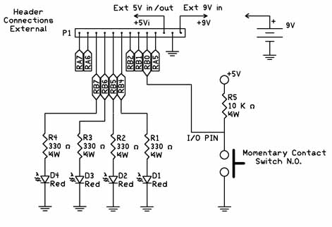
The next thing we need to do is set PortB.0 line to an input. The TRISB = 0 command set all Port B pin/lines to outputs. We can use the INPUT command and add a line in our program INPUT PORTB.0 which will change this line to an input. Alternatively we can use the TRISB = 1 command to set most of Port B lines to outputs with the except of PortB.0 which is set to an input. We will be going over using 8-bit ports and resgisters a little later.
| osccon = %01110100 | 'Set-up internal oscillator at 8 Mhz | |
| define OSC 8 | 'define the oscillator frequency | |
| ANSEL = %01100000 | 'Set RA0-RA4 as digital I/O for LCD leave RA5 and RA6 A/D | |
| trisb = 0 | ' Set Port B to outputs | |
| input portb.0 | ' Set Port B.0 to input | |
| pause 1000 | 'Initalize time for LCD | |
| LCDOUT 254,1, "Binary Counting" | 'Print on LCD line 1 | |
| j var byte | 'Create variable j | |
| i var byte | 'Create variable i | |
| start: | 'Label for start of program | |
| For J = 0 to 15 | 'Start counting loop | |
| lp: | 'Start of loop routine to read switch | |
| if portb.0 = 1 then routine2 | 'If PB.0 = 1 (high) exit loop | |
| goto lp | ' If PB.0 = 0 (low) stay inside loop, stop counting | |
| routine2: | 'If PB.0 = 1 (high) exit loop here | |
| LCDOUT 254,192, " " | 'Clear printing on LCD line 2 | |
| LCDOUT 254,192, "Binary LED # ", #j | 'Print on LCD line 2 | |
| i = j << 4 | 'shift number 4 places to right | |
| portb = i | 'display binary number using LEDs on RB4 to RB7 | |
| pause 500 | 'Delay to give human time to see LED binary number | |
| next j | 'next number | |
| goto start | 'Start from the beginning again |
The Button Command
The PBP Compiler comes equipped with a simple command to read the electrical status of a pin called the Button command. The Button command while useful has a few limitations. One is that you can not read multiple port pin inputs at once, only one pin at a time. We will overcome these button command limitations when using the peek command. But for the time being lets use and understand the button command.
As the name implies the Button command is made to read the status of an electrical "button" switch connected to a Port pin. We can use the same two basic switch schematics, labeled A and B, connected to a I/O pin. The Button Command structure is as follows:
Button Pin, Down, Delay, Rate, BVar, Action, Label
| Pin | Pin number ( 0 – 15), or pin name (e.g Portb.0) | Down | State of pin when button is pressed (0 / 1) | Delay | Cycle count before auto repeat starts (0-255). If 0, no debounce or auto-repeat is performed. If 255, debounce, but no auto-repeat,is performed. | Rate | Auto-Repeat Rate (0-255). | Var | Byte sized variable used for delay/repeat countdown.Should be initialized to 0 prior to use. | Action | State of button to perform GOTO (0 if not pressed, 1 if pressed). | Label | Execution resumes at this label if Action is true. |
Button Example
If we wanted to read the status of a switch off I/O PortB.0, here is a command we will use in the next program.
Button 0, 0,254,0,B1,1,loop
The next program is similar to the previous program, in as much that it performs a binary counting and stops when the button is depressed. This program uses the button command.
The program contains two loops as before, the first loop counts to 15 and the current number's binary equivalent is reflected by the lit LED's connected to port B. The loop continues to count as long as the switch SW1 remains open.
When SW1 is closed the Button command stays inside a smaller internal non-counting loop "lp" where the program remains until the switch SW1 is re-opened. You can switch back and forth between counting and non-counting states.
We use the same scehematic as before.
| osccon = %01110100 | 'Set-up internal oscillator at 8 Mhz | |
| define OSC 8 | 'define the oscillator frequency | |
| ANSEL = %01100000 | 'Set RA0-RA4 as digital I/O for LCD leave RA5 and RA6 A/D | |
| trisb = 0 | ' Set Port B to outputs | |
| input portb.0 | ' Set Port B.0 to input | |
| pause 1000 | 'Initalize time for LCD | |
| LCDOUT 254,1, "Binary Counting" | 'Print on LCD line 1 | |
| j var byte | 'Create variable j | |
| i var byte | 'Create variable i | |
| B1 var byte | 'Create variable B1 for Button Command | |
| start: | 'Label for start of program | |
| For J = 0 to 15 | 'Start counting loop | |
| lp: | 'Start of loop routine to read switch | |
| Button Portb.0, 1,254,0,B1,1,routine2 | 'If PB.0 = 1 (high) exit loop | |
| goto lp | ' If PB.0 = 0 (low) stay inside loop, stop counting | |
| routine2: | 'If PB.0 = 1 (high) exit loop here | |
| LCDOUT 254,192, " " | 'Clear printing on LCD line 2 | |
| LCDOUT 254,192, "Binary LED # ", #j | 'Print on LCD line 2 | |
| i = j << 4 | 'shift number 4 places to right | |
| portb = i | 'display binary number using LEDs on RB4 to RB7 | |
| pause 500 | 'Delay to give human time to see LED binary number | |
| next j | 'next number | |
| goto start | 'Start from the beginning again |
When the program is ran, it begins counting. When the switch is closed all the LEDs will turn off and it stops counting. Open the switch and the counting resumes starting from where it stopped.