
We have an LCD module build on our experimentors board that allows our microcontroller to communicate to us using alpha-numeric text. To use the built-in LCD, we need to add a few lines of additional code.
ANSEL = %01100000 'Set RA0-RA4 as digital I/O for LCD leave RA5 and RA6 A/D
pause 1000
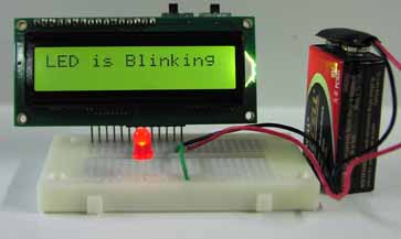
LCDOUT 254,1, "LED is Blinking"
The first line ANSEL = %01100000 sets the pins (or I/O lines) RA0 to RA4 to digital I/O lines. These lines are dedicated to making the LCD function and are not accessible to us for other uses.
The next line Pause 1000, stops the program execution for one second. This is to allow the LCD to complete its own power up initiation and be available for use.
The next line LCDOUT 254,1, "LED is Blinking", clears the LCD screen, positions the cursor on line 1 position 1 then prints the text "LED is blinking" on the LCD. The LCDOUT command structure is discussed below.
Updated Blink Program with LCD Message
Here is the updated PBP program with the three addition lines:
'BLINK with LCD Message PBP Program 1.2
#CONFIG
__config _CONFIG1,_INTRC_IO & _WDT_OFF & _PWRTE_ON & _MCLR_OFF & _LVP_OFF & _CP_OFF
#ENDCONFIG
osccon = %01110100 'Set-up internal oscillator at 8 MHz
ANSEL = %01100000 'Set RA0-RA4 as digital I/O for LCD
Pause 1000
LCDOUT 254,1, "LED is Blinking"
start: 'Start of routine
High PortB.1 'Turn on LED
Pause 500 'Wait 1/2 second
Low PortB.1 'Turn off LED
Pause 500 'Wait 1/2 second
Goto start 'Goto Start and repeat
Download PBP 1.2 Source Download PBP 1.2 Hex File
LCDOUT command:
The LCD Module has two operational modes: text and instruction. Both text and commands are access using the same PBP command "LCDOUT". Text and commands may be combined on the same LCDOUT program line, as is the case with our LCDOUT command. ASCII text are called strings. To print the string “Images” use the Command (LCDOUT “Images”) and the text "Images" will appear on the LCD. The string text to be printed is surrounded by double quotation marks "". These double quotation marks are not printed on the LCD.
To input instructions to the LCD module, you must prefix the instruction with ASCII 254 ($FE). The byte following prefix is seen and treated as a instruction code. Every instruction code must be sent with its own 254 prefix. The clear-screen instruction is ASCII 1.
To clear the LCD screen and place the cursor on the first line first position use the command LCDOUT 254,1
You can also use the hex numbers to send commands. The hex equivalent to decimal number 254 is $FE. So to clear the screen you can also use the command LCDOUT $FE,1.
LCD Instruction Codes
Instruction
Clear Screen
Home position (move cursor top left of display)
Move cursor one character position left
Move cursor one character position right
Scroll display one character position left
Scroll display one character position right
Set cursor porition (DDRAM address)
Set point in character-generator (CG) Ram
Code (Decimal)
1
2
16
20
24
28
128+addr
64+addr
Character Display and off screen characters
The LCD displays the first 16 characters on each line. However, each LCD line can hold 40 characters. When you print past the 16 visible characters, the next 24 characters are in an off-screen memory area. This LCD module has 80 bytes of character memory, arranged appropriately for a 2x40 screen. While the off-screen text can’t be seen on the screen, one could use scroll instructions to scroll and reveal the off screen character text.
Back Light and Contrast Control
Your LCD has a back light that is turned on or off using the back light switch. A potentiometer on the back of the board adjusts contrast of the LCD. You can adjust the contrast control by hand or your optimum viewing.
More information on the LCD is available in the Serial LCD Module manual.
Timing
Before moving on to Binary numbers, lets take a quick look at timing. The PIC microcontroller is accurate in regard to timing. If you built the LED blinker you may have noticed that the LED is turning on-off faster than the program cycle calls for. The program cycle states the LED should turn on for 1/2 second then off 1/2 second where the process repeats. While we set the internal oscillator speed to 8 MHz the PBP compiler does not know the oscillator speed we have set. We have to tell it. While our LED blinking program is a trival timing issue, other processes like serial communication require precise timing to be reliable. We can tell the PBP compiler the speed of the oscillator by adding one line to our program.Define OSC 8 'let pbp know about oscillator value
Updated Blink Program with LCD Message and PBP Set Oscillator
'BLINK with LCD Message and PBP Set Oscillator Program 1.3
#CONFIG
__config _CONFIG1,_INTRC_IO & _WDT_OFF & _PWRTE_ON & _MCLR_OFF & _LVP_OFF & _CP_OFF
#ENDCONFIG
osccon = %01110100 'Set-up internal oscillator at 8 MHz
Define OSC 8 'let pbp know about oscillator value
ANSEL = %01100000 'Set RA0-RA4 as digital I/O for LCD
Pause 1000
LCDOUT 254,1, "LED is Blinking"
start: 'Start of routine
High PortB.1 'Turn on LED
Pause 500 'Wait 1/2 second
Low PortB.1 'Turn off LED
Pause 500 'Wait 1/2 second
Goto start 'Goto Start and repeat
Download PBP 1.3 Source Download PBP 1.3 Hex File
Run this program and the LED timing cycle should be accurate.