
Figure 3 (below) shows how to connect the LCD Modules to PIC microcontrollers, PCs and the BASIC Stamp
The 3-wire connector from a LCD module is set up as follows. Red wire equals +5V, Black wire is the ground and the White wire is the Serial In.
Basic Operation
Once the LCD module is properly connected and configured to match the baud rate of the computer/program that will be talking to it serially, data sent to it will appear on the display. For example, if you send “Hello” then “Hello” appears on the display. The cursor (printing position) automatically moves from left to right.
You can also send instructions to the LCD module. To identify a particular byte as an instruction, precede it with the instruction prefix character, ASCII 254 (0xFE hex, 11111110 binary). The interface treats the byte immediately after the prefix as an instruction, then automatically returns to data mode.
Example: The clear-screen instruction is ASCII 1. To clear the screen, send <254><1> (where the <> symbols mean single bytes set to these values, not text as typed from the keyboard).
LCD Instruction Codes
Instruction
Clear Screen
Home position (move cursor top left of display)
Move cursor one character position left
Move cursor one character position right
Scroll display one character position left
Scroll display one character position right
Set cursor porition (DDRAM address)
Set point in character-generator (CG) Ram
Code (Decimal)
1
2
16
20
24
28
128+addr
64+addr
Self-Test Mode
The LCD module has a self-testing mode that will print the current jumper setting’s baud rate and mode (true/inverted). To enter self-test mode, connect the serial in line to ground (for True) or +5V (for Inverted) upon LCD module startup. NOTE: If serial-in line is improperly connected for Self-Test mode, for instance connected to +5V when jumpers are set for True mode, the LCD display will remain blank.
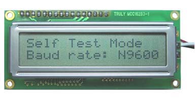
The module stays in self-test mode as long as the serial in line is held either high (inverted mode) or low (true mode). LCD module may be exited from self-test mode on the fly by simply connecting the serial-in line to a serial source.