
Figure 1 (below) shows the major features and configuration options of the LCD-02 circuit board.
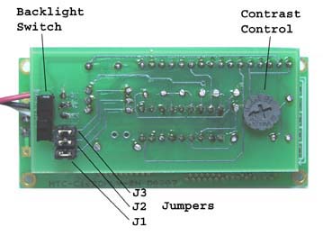
Figure 1
Contrast Adjustment
The contrast control is usually set fully clockwise at the factory. You can adjust the contrast control by hand.
Setting the Baud Rate
Figure 2
Set the baud rate in accordance with figure 2. The LCD Modules are factory set at 1200 Baud True. Remove jumpers to adjust baud rate accordingly. At all baud rates serial data is set at 8 data bits, 1 stop bit, no parity.
NOTE: The interface reads the baud-rate jumpers only at startup. Do not change the jumper setting while the LCD module is active as this will not change the baud rate! Only change the baud rate jumper settings with the LCD module off to insure proper baud rate upon power up of the LCD module.