
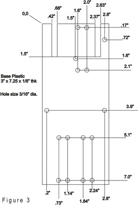
 To begin we start with the plastic frame cut out of 1/8” thick clear acrylic plastic, see figure 3 (left) . The chassis uses 3 pairs of 90
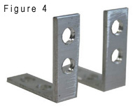 degree servomotor brackets, see figure 4 to hold the servomotors to the chassis.
The right and left drive servomotors are continuous rotation servomotors. You may use the parallax CR servomotors, HiTec’s new HSR-1425CR, or modified HS-425 servomotors. The servomotor that rotates the CMU camera up and down is a standard HS-322 or HS-325 servomotor.
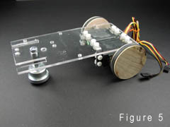
We start construction by mounting the right and left drive servomotors to the bottom rear of the chassis. Each servomotors is mounted using two 90 degree servomotor brackets along with 6-32 machine screws, split lock washers and nuts. Then we mount the front caster style wheel, see figure 5. The caster style wheel uses a ¼-20 screw though the chassis, into a ¼-20 coupler to which the caster screws into from the other side of the coupler.
Wheel Construction
If you want to make your own servomotor wheels as shown in the photographs you can the follow the wheel construction instructions at the end of this article. If you have suitable servomotor wheels approximately 2.0” in diameter you can use them.
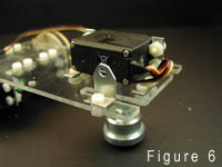 Next we mount the up and down servomotor to the top front of the chassis using two 90 degree servomotor brackets, 6-32 machine screws, lock washers and nuts. A small 90 degree clip is mounted behind the servomotor using a 6-32 screw, washer and nut, see figure 6.