
Choosing a proper target object is essential to having the C-Bot accurately follow your target. Here are a few general guidelines.
Primary Color:
I have gotten good results with monochromatic targets. A red ball, or orange basketball make good targets.
Contrast:
To successfully track a target the target should contrast with the background. For instance, like a red ball against a white background. The better the contrast the easier it is to track the target.
False targets.
In the process of tracking a target, the camera can lock onto a similar colored object and misinterpret that colored object for the target. For instance if the red ball rolled in front of red construction paper, the camera could lock onto the paper and disregard the ball. So be aware that components in the background shouldn’t color match your target.
Controlling the CMU Camera (Program Function)
I have used the PICBasic Pro compiler to write my controller firmware. The PIC program controls and interrogates the CMU-01 through a 38,400 Baud TTL serial link. In the beginning of the program the PIC outputs a text message to the LCD and sends multiple resets to the camera to prepare it for use.
LCDOut "C-Bot Tracker"
For x = 0 TO 4
SerOut2 tx, 6, ["RS", 13]
Pause 100
Next x
Next we send a DM command which adds a small character delay so we don’t over run our PIC serial communications.
SerOut2 tx, 6, ["DM 3", 13]
GoSub ack
Pause 250
The following code blinks the CMU-01’s green LED. The blinking LED assures the user that proper communication is established between the CMU camera and the PIC.
LCDOut "Blink Track LED"
For x = 0 TO 7
SerOut2 tx, 6, ["L1 1", 13]
Pause 100
SerOut2 tx, 6, ["L1 2", 13]
Pause 100
Next x
The following code group sets the CMU-01 camera’ internal registers. We are setting the lighting for fluorescence lights, Color Mode; Auto white balance on. The white balance command takes approximately five second to adjust.
SerOut2 tx, 6, ["CR 45 7 18 44 19 33", 13]
GoSub ack
LCDOut "Color & AE on"
LCDOut 254, 192, "Wait 5 sec."
Pause 5500
The following programming line commands the CMU-01 to turn off the Color Mode balance.
SerOut2 tx, 6, ["CR 45 7 18 40 19 32", 13]
GoSub ack
The following programming lines put the CMU-01 into Poll Mode (PM). This restricts the camera to sending a single packet of information when a processing function is called.
SerOut2 tx, 6, ["PM 1", 13]
GoSub ack
The following programming lines put the CMU-01 into Raw serial transfer Mode (RM) where the “ACK\r and “NCK\r” confirmations are not sent after each command.
SerOut2 tx, 6, ["RM 1", 13]
GoSub ack
The following code group sends the text message to the user vis the LCD to place a target in front of the C-bot. The user is given five second to accomplish this task.
LCDOut "Place Target"
LCDOut 254, 192, "5 sec."
For x = 0 TO 10
SerOut2 tx, 6, ["L1 1", 13]
Pause 250
SerOut2 tx, 6, ["L1 2", 13]
Pause 250
Next x
In addition to the text message the green LED blinks. In case the LCD is turned off to conserve power, the blinking LED also informs the user to place their target in front of the lens.
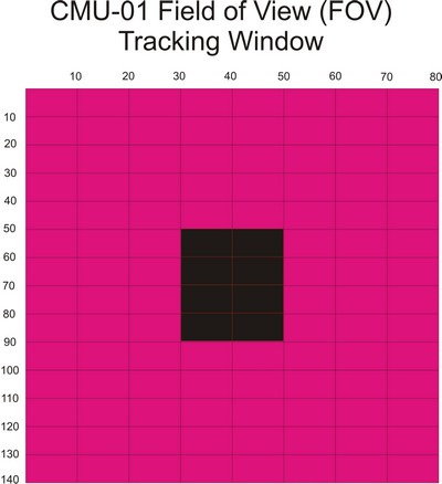
The next command tells the CMU-01 to Track the color found in the Window (TW). When this command is initiated the CMU-01 shrinks its field of view window to ¼ size of its standard resolution captures the color in the window, then restores the window to its original size. To get an idea of the track window, look at figure 2. The black section represents the ¼ size capture color window.
The next command puts the text message on the LCD that the target has been captured.
LCDOut "Target Captured"
The following command reads a switch position to determine whether the program should operate in RUN or TEST mode.
IF PORTB.4 = 1 Then RT2
RT1 represents the RUN mode and RT2 jumps to the TEST mode.
Before we move further into the program description we need to look at the data packet the CMU-01 delivers to us when we issue a Track Color (TC) command
M Packet in Raw Mode
The following is a byte description of the M packet serial data we receive from the CMU-01. By placing the serial data in an array, we can have the PIC microcontroller read the data in the serial array and perform functions depending upon its value. Interpreting the M-Packet data is the heart of the program.
ASCII Byte#
A 0
C 1 The first three bytes equal ACK
K 2
CR 3 forth byte equals a Return
255 4 Synchronize byte
M 5 M packet ID
MX 6 Middle Mass x value
MY 7 Middle Mass y value
X1 8 Leftmost X corner
Y1 9 Leftmost Y corner
X2 10 Rightmost X corner
Y2 11 Rightmost Y corner
PIX 12 Number of pixels in tracked region
CONF 13 Confidence Value
: 14 Colon (Punctuation Mark)
Both the Test and Run modes read the M packet.
Based upon the values read in the M packet the robot either moves to track (Run) or reports the information (Test) on the LCD.