
The program is written using the PICBasic Pro compiler from microEngineering. The hex file for each program is avialable for downloading at the end of each program listing. This program implements the power saving functions discussed, and adds a new one. The program causes the microcontroller to enter a one-second sleep mode. During sleep the microcontroller draws minimum power. Each time the microcontroller wakes up from its sleep, it powers up the compass for five milliseconds, takes a directional reading from the compass, transmits the directional data out on its serial line, then goes back to sleep for one-second. The process repeats continually. This allows the circuit to draw minimal power for the power supply.
PIC Program to Output Numeric information
'Navigation Board Program #1
'PIC16F84
'SEROUT Numeric Data
'Initialize Variables & Ports
b0 VAR BYTE
b1 VAR BYTE
TRISA = 0 'Set TRISA to make Port A all outputs
TRISB = 15 'Set TRISB to make PortB, RB0-RB3 inputs RB4-RB7 outputs
'Monitoring Routine
start:
Sleep 1 'low powermode 1 seconds
PORTB = 192 'apply power to compass
Pause 5 'wait 5 ms for power to settle
b0 = PORTB 'read compass and hold results in b0
PORTB = 240 'Turn off power to compass
b1 = b0 & 15 'Mask 4 bits and store results in b1
'Send info to serial display
SerOut PORTA.2,6,[$FE,$01," ",#b1]
GoTo start
End
*to change this program to transmit numeric data change the serout line to:
SerOut port A.2, 6,,[b1]
This second program translates the numeric information into text readable compass directions before transmitting the data.
PIC Program to Output ASCII Compass Data
'Navigation Board Program #2'PIC16F84
'SEROUT Numeric Data
'Initialize Variables & Ports
b0 VAR BYTE
b1 VAR BYTE
TRISA = 0 'Set TRISA to make Port A all outputs
TRISB = 15 'Set TRISB to make PortB, RB0-RB3 inputs RB4-RB7 outputs
'Monitoring Routine
start:
Sleep 1 'low powermode 1 seconds
PORTB = 192 'apply power to compass
Pause 5 'wait 5 ms for power to settle
b0 = PORTB 'read compass and hold results in b0
PORTB = 240 'Turn off power to compass
b1 = b0 & 15 'Mask 4 bits and store results in b1
'Send info to serial display
IF b1 = 14 Then SerOut PORTA.2,6,[$FE,$01," North"]
IF b1 = 12 Then SerOut PORTA.2,6,[$FE,$01," North-East"]
IF b1 = 13 Then SerOut PORTA.2,6,[$FE,$01," East"]
IF b1 = 9 Then SerOut PORTA.2,6,[$FE,$01," South-East"]
IF b1 = 11 Then SerOut PORTA.2,6,[$FE,$01," South"]
IF b1 = 3 Then SerOut PORTA.2,6,[$FE,$01," South-West"]
IF b1 = 7 Then SerOut PORTA.2,6,[$FE,$01," West"]
IF b1 = 9 Then SerOut PORTA.2,6,[$FE,$01," North-West"]
GoTo start
End
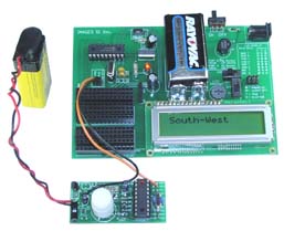
The program transmits ASCII text relating to the compass direction.
Testing Microcontroller Navigation Board
All that is left is to check the serial output of the navigation board. To do this I used a PICX experimenter's board that has a serial LCD display. I set the LCD display on the PICX board to read 9600 Baud N. I connected the Navigation Board's SER OUT to the Ser In, the results are shown in figure 15.
Going Further
The Navigation Board is ready for expansion. There are multiple power leads as well as leads for all I/O lines on the PIC 16F84/16F628 microcontrollers. Using this contact points one can easily expand the microcontrollers program and connect to these open I/O lines.