You have a number of options when using a microcontroller. The microcontroller can supply direction information to a mobile robot or PC.
Building the Microcontroller Navigation Board
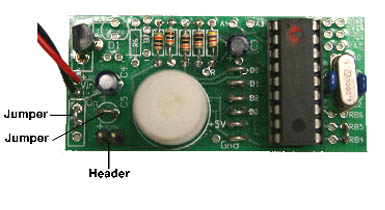
One only needs a handful of additional components to our existing visual compass board to implement a microcontroller. Place and solder R5, a 4.7K resistor. Capacitors C1 and C2 are 22 pF with a 4 MHz xtal between them. Place and solder a 18-pin IC socket.
Power consumption is usually an important consideration for mobile robots. Because of this we have a number of power saving features that may be incorporated on the board.
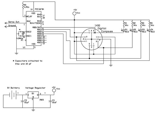
Figure 10 simply adds a microcontroller to the schematic. The four output pins (pin 3) from the compass is read by four I/O lines on the microcontroller. This schematic allows visual indication of the compass status as well as directional reading by the microcontroller. The microcontroller reads the 4 lines and produces a 4-bit number based on the status of the output pins. In table 1 the equivalent number is shown in the I/O read column. This number may be sent out serially on an open I/O line.
The reason the decimal equivalent number we see on the LED display isn't the same as the number in the I/O read column is because the microcontroller reads the logic on the lines the opposite of the visual indication of the LED's. Looking at the schematic, shown in figure 10, when the cathode of the LED is at 5 volts, the LED is off (ungrounded). The microcontroller sees this LED line as a binary 1(or logic) 1. When the line is active by the compass, the line drops to zero (ground), which lights the LED. The microcontroller now sees this line as a binary 0.
| |
|
|
|
| |
|||
| |
|
|
|
|
|
|
|
|
|
|
|
|
|
|
|
|
|
|
|
|
|
|
|
|
|
|
|
The number the microcontroller sees is outputted serially on RA2. The serial information may be directed to another microcontroller or PC. The external CPU interprets the number it receives as a direction.
Power Saving Techniques
There are a few techniques we can employ to reduce power consumption.
First Power Reduction Technique
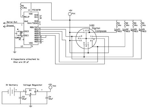
Figure 11 shows the first reduce power savings. We change the ground jumper on the board from the center lead and left lead to the center lead and right lead. This connects the ground to the Microcontroller RB4 pin. Now add a jumper between RB4 and RB5 leads, see figure 12. To take a reading from the compass, the microcontroller supplies power to the compass by bringing pins RB4 and RB5 to ground. When the reading is finished, the microcontroller turns power off to the compass by bringing RB4 and RB5 lines to +5V. Using this procedure, full power is only needed when taking compass readings that may be accomplished in a few milliseconds. Additional power savings can be realized by substituting the standard 7805-voltage regulator for a higher efficiency 5-volt LM2936 regulator. This voltage regulator reduces the standby current from 5 mA to well under 1 mA.
Second Power Reduction Technique
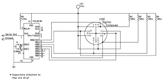
Figure 13 is a schematic that incorporates the first power reduction options. In this schematic we have removed the LEDs that provide the visual indication and replaced them with jumpers. The 1 K resistors (R1, R2, R3 and R4) are substituted with 10K resistors. The maximum power required for the display section varies between 5 mA and 10 mA, depending upon whether 1 or 2 LEDs were lit. This technique reduces the power for this section to a maximum of 1 mA. Completed circuit is shown in figure 14.