Images Scientific Instruments Inc. sitemap


UFO Detector Online Construction Manual

UFO Detector - how do you detect something you're not sure exists?

Common Electromagnetic Disturbances

Considerations for UFO Detector Kit Construction

Continuing UFO PCB Construction

Housing the UFO Detector

Bibliography

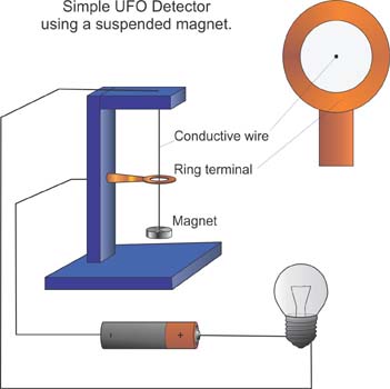
Over the years many UFO sightings have reported magnetic and electromagnetic disturbances. The UFO Detector is designed to sense these disturbances and will signal their presence by flashing an LED and beeping.


UFO Detector Clear

Do UFO's; Unidentified Flying Objects exist? Of course they exist! UFO sightings are reported all over the globe by thousands of people. The real question is whether UFO's are interstellar vehicles visiting Earth? Most UFO sightings can be classified as misidentified aircraft, planets or other aerial phenomena, but not all of them. There is that small percentage of UFO reports that can't be explained by any known aircraft or natural phenomena. It is these reports that create an exciting possibility.

Granted these possibilities attract fringe personalities and hucksters that ought not be taken seriously. But one should not discount the entire subject of UFO's based upon the psycho-ramblings of a few individuals or groups. UFO enthusiasts know the odds are stacked against them regarding credibility.

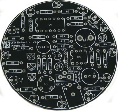
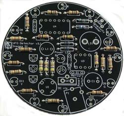
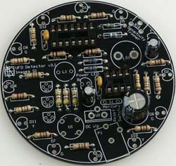
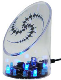
UFO's can be debated intelligently on both sides of the fence. This article will not enter the debate. But if UFO's has ever aroused your curiosity you may be interested in building a UFO Detector from one of the kits we offer in multiple color options, see figures 1. Figure 1 is our UFO-02A. Our kits include all components needed to build the circuit, housing sold separately.

UFO Detector Video - The current version UFO Detector works the same way. Resetting is a bit different. The transparent case and the electronics are separate. So one lifts off the transparent case first then turns the electronics upside down to reset.

UFO Detector Kit Page
Detector Kit
(Kits Require assembly, soldering, gluing, etc.)
Case Sold Separately
Available with Blue or Red LEDs

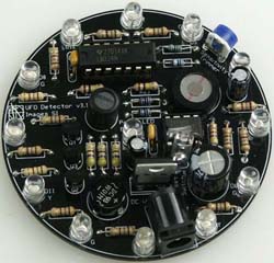
UFO Detector Assembled
Detector (Assembled & Tested)
Available with Blue or Red LEDs

UFO Detector Bundle
Detector (Assembled & Tested) with book
Available with Blue or Red LEDs


Back to Table Of Contents

UFO Detector - how do you detect something you're not sure exists?

We rely on information reported from past UFO sightings. Reports that detail major electrical and magnetic disturbances. See bibliography at the end of this article.

simple UFO detector

Various electromagnetic disturbances have been reported along with UFO sightings. For instance, a running car engine will stumble, cough, and stall. Magnetic compasses have been known to swing wildly around and around during UFO sightings. If this information is accurate, we can use these side effects to make a UFO detector.

Using the magnetic anomaly side effect is not a new idea. There are a number of simple plans around the Internet that use a magnet suspended on a conductive wire through a ring terminal, see Figure 3. When something causes the magnet to move, the conductive wire touches the ring terminal completing an electric signaling circuit that sounds an alarm or causes a light to turn on.

A simple but far more sensitive UFO detector, employing the same principle, can be made from a standard magnetic compass/sensor. You place the compass down, away from any magnetic fields, electric fields and ferrous materials. Let the compass needle settle down and point to Earth's magnetic north. The compass-detector is now set, you sit and watch the compass needle. If the needle starts jumping around and swinging wildly you may have detected a magnetic anomaly that could signal a UFO event. However, just because the needle started jumping around doesn't always mean it's detecting a UFO. You first have to rule out a number of common reasons that could cause the compass needle to act erratically.

Back to Table Of Contents

Common Electromagnetic Disturbances

You have to rule out a number of common reasons that could cause your detector to act erratically.

For instance, if somebody passed the sensor holding a strong permanent magnet, or carrying a quantity of ferrous materials. Or if the sensor is lying close to an electrical line and someone switches electrical power on or off. Placing the sensor close to any electrical device may also cause the detector to react erratically. After eliminating these common terrestrial triggers you may be left with a legitimate event to investigate.

UFO sightings are rare events. So unless you plan to stare at your detector for days, weeks, months or years at a time, you need to automate the process. That’s where our UFO Detector comes in. Our UFO Detector contains a sensitive miniature magnetometer interfaced to a micro-controller that is designed to sense these electromagnetic disturbances. The UFO Detector will operate 24 hours a day, seven days a week while plugged in.

Circuit Function

Our microcontroller monitors the amplified signal from a coil inductor which is a magnetometer for any anomalies. When it detects a magnetic anomaly, the microcontroller signals by flashing the 13 LED lights simultaneously and beeping. When the unit is in monitoring mode, the LEDs light in a moving circular pattern around the edge of the circuit board.

UFO Detector Function

When power is applied to the circuit (or reset), the microcontroller waits a second before beginning active scanning of the inductor coil sensor. After the initial second has elapsed the microcontroller signals the LEDs to light in a moving circular pattern and beeps once signaling it’s in detector mode.

The microcontroller continually scans the inductor coil sensor for any changes in the magnetic field. If it detectors an anomaly the detector beeps an alarm and all LEDs blink simultaneously. The alarm will continue until the circuit is reset.

The UFO Detector may be purchased as a kit with all the components ready to be assembled, or completely assembled, tested and ready to go. The kit is less expensive than the assembled version. For anyone wanting to build the kit version, the directions to do so follow.

Back to Table Of Contents

Considerations for UFO Detector Kit Construction

To build the UFO Detector kit, you will need to identify, mount and solder electrical components onto a printed circuit board. Glue a couple of plastic components together. Cut out a transparent label with a scissor and finally trim the label with an exacto knife.

If the construction sounds like too much work for you or you don't think you can do it properly, you can buy the kit assembled and tested. If you are up to building this kit, then let's continue.

Circuit Construction

ufo detector schematic

The UFO Detector schematic is shown in Figure 4 (above). Using the printed circuit board (PCB) you simply mount and solder the components. The topside of the PC board has white silkscreen depicting the parts placement, see Figure 5. Mount  the components to the topside of the board. Solder the components from the bottom side of the board and clip away any excess wire.


The topside of the pcb board has white silkscreen depicting the parts placement, see figure 4. Mount the components to the topside of the board. Solder the components from the bottom side of the board and clip away any excess wire.

simple UFO detector


Back to Table Of Contents

Continuing UFO PCB Construction

Resistors

Begin construction by mounting and soldering the 13 - 180 ohm resistors in positions R1 - R12, and R24 (color bands brown, gray, brown, gold). R13 is an 18K ohm 1% resistor (color bands brown, gray, black, red, brown). R14 is a 4.7K ohm resistor (color bands yellow, purple, red). R15 is a 3K ohm 1% resistor (color bands orange, Black, black, brown, brown). The three 470 ohm resistors mount in R17, R18, and R20 ( color bands yellow, purple, brown). The two 1K ohm 1% resistors mount in R19, and R21 (color bands brown, black, black, brown, brown). R22 & R23 are 100K ohm resistors (color bands brown, black, yellow).

Capacitors

Next mount & solder the 8-pin and 14-pin sockets in U3 & U4. The 470uF capacitor should be mounted in C1. The 10uF capacitors are C2 &C3. C4 & C5 are .1uF capacitors.

Now mount and solder the three 2N3904 transistors (Q1, Q2 & Q3). The Bridge rectifier should be mounted and soldered in U1. L1 is a 100uH inductor. Mount and solder the speaker (LS1) next. The 7805 voltage regulator is U2. Be sure to orient it to match the printed silkscreen.

Mercury Switch

The tilt switch is an important component. It allows you to reset, or turn off, the UFO detector by simply turning it upside down.

The mercury tilt switch is mounted upside down. Bend the leads as shown in the in image to the left and mount and solder in S1. Next mount the 20K potentiometer in R16 and the power jack (P1).
Completed Circuit
You are now ready to install the 13 LEDs (D1 - D13). Twelve LEDs surround the board with one in the center. The LEDs only pass current in one direction. To orient them correctly, align the shorter lead of the LED to the flat side of the circle printed on the pcb, refer back to Figure 5.

Back to Table Of Contents

Housing the UFO Detector

The finished UFO Detector board will occupy a space of approximately 3" in diameter by 1" high.

The detector needs to be housed in a non-ferrous material. A ferrous material like iron would affect the compass operation. Suitable non-ferrous housing materials include the following materials: plastic, wood, brass, foam board and aluminum. If you would like an almost ready made housing the Testor Model company sells two different styles of UFO models. One is a Roswell UFO model number 555 and the UFO model is Testor's part number 576X. Either model is large enough to hold the detector inside and would make a suitable enclosure.


The completed circuit  should sit flat inside the housing you choose. To accomplish this four self-adhesive 1/4" rubber bumpers are placed on the underside of the board in approximately equal distance from each other.

feet You are now ready to use your UFO Detector.


Back to Table Of Contents

Bibliography

Information reported from past UFO sightings. Following reports detail major electrical and magnetic disturbances.

http://www.nicap.dabsol.co.uk/92apsiee.htm

Fifty-Six Aircraft Pilot Sightings Involving Electromagnetic Effects

Richard F. Haines, Ph.D., NICAP


Reports of anomalous aerial objects (AAO) appearing in the atmosphere continue to be made by pilots of almost every airline and air force of the world in addition to private and experimental test pilots. This paper presents a review of 56 reports of AAO in which electromagnetic effects (E-M) take place on-board the aircraft when the phenomenon is located nearby but not before it appeared or after it had departed. Reported E-M effects included radio interference or total failure, radar contact with and without simultaneous visual contact, magnetic and/or gyro-compass deviations, automatic direction finder failure or interference, engine stopping or interruption, dimming cabin lights, transponder failure, and military aircraft weapon system failure.

http://www.narcap.org/technicalreports.htm

A Preliminary Study of Fifty Seven Pilot Sighting Reports Involving Alleged Electro-Magnetic Effects on Aircraft Systems

Richard F. Haines, Ph.D. and Dominique Weinstein


This preliminary report presents the findings of a comprehensive review of over fifty years of pilot reports in which permanent or transient electro-magnetic (EM) effects occurred on in-flight aircraft systems allegedly as a direct or indirect result of the relatively near presence of one or more unidentified aerial phenomena (UAP). From a total of 1,300 reports fifty seven (4.4%) were found that involved E-M effects. The most commonly reported UAP shape is round or oval. Interestingly, most of the E-M effects occurred when the UAP was nearby the aircraft. These findings are potentially important and deserve further in-depth study and confirmation by obtaining additional high quality aviation reports.

UFO Detector Kit Page
Back to Table Of Contents