
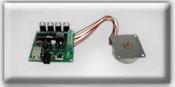
 USB Stepper Motor Kit
|
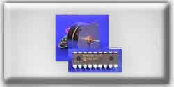 PIC Stepper Motor Kit
|
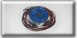 Stepper Motor
|
The first program was fine for demonstrating how to control a stepper motor with a PIC Micro, but was severely limited to the one mode of operation preprogrammed into it. In this next program, we will make the program controllable by external user input in the form of four switches: SW1 will incrementally increase the delay variable, thereby slowing the rotation of the motor. SW2 does the opposite. SW3 halts all operation while the switch is pressed. SW4 reverses direction of the motor (CW to CCW or vice-versa) while it is closed (pressed).
listing 2
' Second stepper motor controller program
' Responds to user input by changing speed or direction
Symbol delay = B0
delay = 100
forward:
high 0
pause delay
low 0
high 1
pause delay
low 1
high 2
pause delay
low 2
high 3
pause delay
low 3
goto check
reverse:
high 3
pause delay
low 3
high 2
pause delay
low 2
high 1
pause delay
low 1
high 0
pause delay
low 0
goto check
check:
if pin4 = 0 then timeup
if pin5 = 0 then timedn
if pin6 = 0 then halt
if pin7 = 0 then reverse
goto forward
timeup:
delay = delay + 5
pause 50
if delay > 250 then max
if pin4 = 0 then timeup
goto check
timedn:
delay = delay - 5
pause 50
if delay <20 then min
if pin5 = 0 then timedn
goto check
halt:
if pin6 = 0 then halt
goto check
max:
delay = 245
goto check
min:
delay = 25
goto check
' use b0 as the delay variable
' delay will begin at 100 ms
' turn on Q1
' wait for delay ms
' turn off Q1
' turn on Q2
' wait for delay ms
' turn off Q2
' turn on Q3
' wait for delay ms
' turn off Q3
' turn on Q4
' wait for delay ms
' turn off Q4
' check the status of switches
' turn on Q4
' wait for delay ms
' turn off Q4
' turn on Q3
' wait for delay ms
' turn off Q3
' turn on Q2
' wait for delay ms
' turn off Q2
' turn on Q1
' wait for delay ms
' turn off Q1
' check the status of switches
' if nothing pressed, continue
' increase delay by 5 ms
' pause for 50 ms
' check switches again
' decrease delay by 5 ms
' pause for 50 ms
' check switches again
'check switches again
' cap the delay at 245 ms
' check switches again
' limit the delay to 25 ms
' go back and check switches
End Listing 2
As you can see by looking at the schematic (Figure 7), the "switches" used in this circuit are pieces of jumper wire on a breadboard. The inputs (B0-B3) are kept high via Vcc through a 10K resistor. Theses switches are activated by grounding them via another piece of jumper wire.
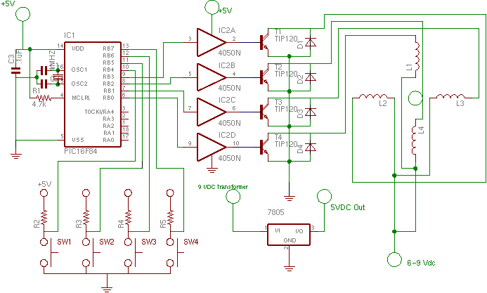
A note on the previous two listings: the minimum delay used in the programs was 25 ms. Depending on the clock speed of your crystal, 25 ms may be either too fast or too slow for the rotor to move. If you are having problems getting these programs to work, this is a likely culprit (further troubleshooting information).