
 USB Stepper Motor Kit
|
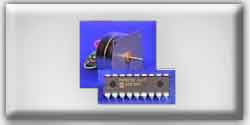 PIC Stepper Motor Kit
|
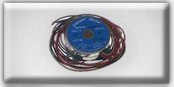 Stepper Motor
|
Stepper motors consist of a permanent magnetic rotating shaft, called the rotor, and electromagnets on the stationary portion that surrounds the motor, called the stator. Figure 1 illustrates one complete rotation of a stepper motor. At position 1, we can see that the rotor is beginning at the upper electromagnet, which is currently active (has voltage applied to it). To move the rotor clockwise (CW), the upper electromagnet is deactivated and the right electromagnet is activated, causing the rotor to move 90 degrees CW, aligning itself with the active magnet. This process is repeated in the same manner at the south and west electromagnets until we once again reach the starting position.
In the above example, we used a motor with a resolution of 90 degrees or demonstration purposes. In reality, this would not be a very practical motor for most applications. The average stepper motor's resolution -- the amount of degrees rotated per pulse -- is much higher than this. For example, a motor with a resolution of 5 degrees would move its rotor 5 degrees per step, thereby requiring 72 pulses (steps) to complete a full 360 degree rotation.
You may double the resolution of some motors by a process known as "half-stepping". Instead of switching the next electromagnet in the rotation on one at a time, with half stepping you turn on both electromagnets, causing an equal attraction between, thereby doubling the resolution. As you can see in Figure 2, in the first position only the upper electromagnet is active, and the rotor is drawn completely to it. In position 2, both the top and right electromagnets are active, causing the rotor to position itself between the two active poles. Finally, in position 3, the top magnet is deactivated and the rotor is drawn all the way right. This process can then be repeated for the entire rotation.
There are several types of stepper motors. 4-wire stepper motors contain only two electromagnets, however the operation is more complicated than those with three or four magnets, because the driving circuit must be able to reverse the current after each step. For our purposes, we will be using a 6-wire motor.
Unlike our example motors which rotated 90 degrees per step, real-world motors employ a series of mini-poles on the stator and rotor to increase resolution. Although this may seem to add more complexity to the process of driving the motors, the operation is identical to the simple 90 degree motor we used in our example. An example of a multipole motor can be seen in Figure 3. In position 1, the north pole of the rotor's permanent magnet is aligned with the south pole of the stator's electromagnet. Note that multiple positions are aligned at once. In position 2, the upper electromagnet is deactivated and the next one to its immediate left is activated, causing the rotor to rotate a precise amount of degrees. In this example, after eight steps the sequence repeats.
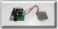
The specific stepper motor we are using for our experiments (ST-02: 5VDC, 5 degrees per step) has 6 wires coming out of the casing. If we follow Figure 5, the electrical equivalent of the stepper motor, we can see that 3 wires go to each half of the coils, and that the coil windings are connected in pairs. This is true for all four-phase stepper motors.
However, if you do not have an equivalent diagram for the motor you want to use, you can make a resistance chart to decipher the mystery connections. There is a 13 ohm resistance between the center-tap wire and each end lead, and 26 ohms between the two end leads. Wires originating from separate coils are not connected, and therefore would not read on the ohm meter.