Electrical Heating (PWM)
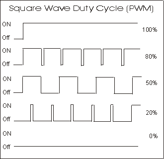
On the previous page, we activated nitinol wire using a basic DC current. While this works, it is easy to overheat and potentially damage the nitinol wire. We can construct a pulse width modulation (PWM) circuit. Activating nitinol wire using pulse width modulation has distinct advantages. Pulse Width Modulation turns the current on and off to the nitinol wire very quickly. The oscillating on-off of the power allows the heat to flow to cold spots making for more even heating of the wire (reduces hot spots). The duty cycle of the square wave output can be varied from fully on 100% to fully off 0%. The duty cycle of the square wave can be varied to generate a degree of proportional control over the contraction. These factors allow us to activate the nitinol wire with better control for longer periods of time without causing heat damage to the crystalline structure of the nitinol alloy.
Figure 9 PWM - Duty Cycle

The chart on the left shows the heat response of nitinol wire. You can guage from the chart as the Nitinol wire is heated it contracts and as it cools it can expand again. This is the same information that's been provided before. What is new is the "H" area in the chart, this represent the hyerstesis. There is a hysteresis curve for every Nitinol alloy. Hysteresis is a retardation of movement when there are thermal changes acting upon the Nitinol. (as if from viscosity or internal friction).
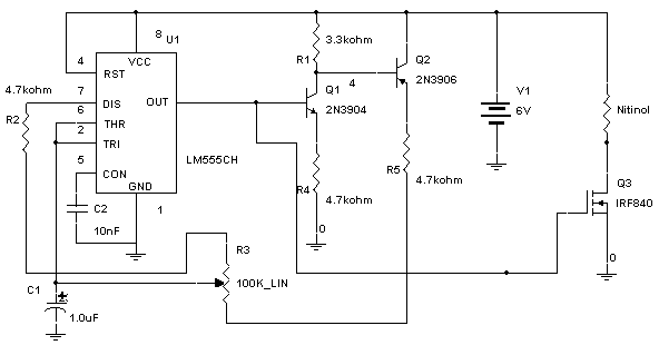
The PWM circuit is made from a 555 timer, (see figure 11). By using two transistors Q1 and Q2 and potentiometer with the 555 timer we can create an output with a relative constant frequency with a variable duty cycle. When the output from the timer (pin 3) goes high, both transistors Q1 and Q2 turned on. The current through Q1, R3 and portion of the Potentiometer (R4) designated RA charges the timing capacitor C1. When the voltage on C1 reaches 2/3 Vcc, the output on the 555 timer (pin 3) goes low.
At this point both transistors Q1 and Q2 turn off. Capacitor C1 begins to discharge through the portion of the potentiometer (R4) designated as RB and R5 via pin 7 (Discharge pin) of the 555 timer. When the voltage on C1 drops to 1/3 Vcc the output switches high and the timing cycle repeats.
The output of the 555 timer (pin 3) connects to a MOSFET transistor that switches the current on and off to the nitinol wire. If the current from the PWM circuit is too powerful to control the nitinol wire proportionally, place an 8-ohm (2 watt or greater) resistor in series with the nitinol wire to reduce power.


