
The LCD has eight unused characters in RAM (Random Access Memory) that the user may define and use. Each character is defined by a 5x8-pixel pattern. The standard character generator of the HD44780 holds the 5x8-pixel patterns for its standard ASCII characters in ROM (Read Only Memory) and cannot be changed.
Each custom character is defined by an 5x8-pixel pattern. The pattern consists of five pixels across each row and eight rows high. Each 5-pixel row is represented by one byte. See the illustration below.
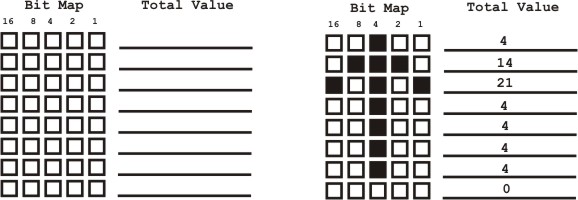
Each box in the bit map has a value listed at the top of its column. When the box is colored in the value is added to all the colored boxes across each row and placed in the total value column to the right. Those total values are the byte values you will use to define your custom characters. Each character requires eight bytes of information to be defined. An up pointing arrow character is shown for example.
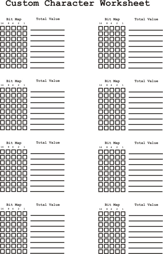
A worksheet is provided to help you to define the eight custom characters. You do not need to define all eight characters; you can define just one character if that is all you need.
Writing Custom Characters to CG RAM
Program examples follow this general outline.
1) Set pointer to beginning of CG RAM (memory location 64) on LCD display
SerOut PORTB.0,4,[254,64]
2) Send bytes representing bit patterns into CG RAM. The LCD controller automatically increments CG RAM addresses, as bytes are transmitted.
3) Leave CG RAM by issuing a control command such as clear LCD screen.
SerOut PORTB.0,4,[254,1] 'clear screen
4) The custom characters are the first 8 character positions in the LCD CG memory (memory locations 0 to 7). To print custom characters, use the character position. The following commands prints the first two customer characters.
SerOut PORTB.0,4,[0] 'Print 1st Custom Char.
SerOut PORTB.0,4,[1] 'Print 2nd Custom Char.
PICBasic Pro PROGRAM EXAMPLE 1.1 - using PIC16F628
'Programming custom characters into the LCD RAM
CMCON = 7 ' Disable Analog comparators
cnt VAR BYTE
char VAR BYTE
Data 4,0,4,4,8,17,17,14 'upside down question mark
Data 4,4,31,4,4,4,4,4 'cross
Data 4,14,21,4,4,4,4,0 'up arrow
Data 0,4,4,4,4,21,14,4 'Down arrow
Data 3,2,2,2,2,14,30,14 'music note
Data 14,17,17,31,27,27,31,0 'locked
Data 14,16,16,31,27,27,31,0 'unlocked
Data 30,28,28,18,1,0,0,0 'microsoft icon
Pause 1000
SerOut PORTB.0,4,[254,1] 'clear screen
Pause 100
SerOut PORTB.0,4,[" Gen. Graphics"]
SerOut PORTB.0,4,[254,192] 'move to line 2
Pause 4
SerOut PORTB.0,4,["Loading CG RAM"]
Pause 250
SerOut PORTB.0,4,[254,64]
Pause 4
For cnt= 0 TO 63
Read cnt, char
SerOut PORTB.0,4,[char]
Pause 4
Next
SerOut PORTB.0,4,[254,1] 'clear screen
Pause 4
SerOut PORTB.0,4,["Custom Graphics"]
'Move to second line
SerOut PORTB.0,4,[254,192] 'move to line 2
Pause 4
For cnt= 0 TO 7
SerOut PORTB.0,4,[cnt," "] 'Print character then space
Next
Program Output
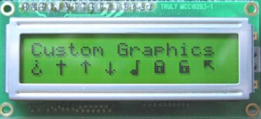
Program Function:
Program 1.1 uses a PIC16F628 connected to the LCD display. Port B pin 0 serially transmits data to the serial LCD. The program uses the 16f628 on chip EEPROM to store the custom character's bit maps. The baud rate used in the example is N2400.
Animation
Basic animations may be created by rapidly displaying successive custom characters in the same LCD screen position.
Animation using external memory
You can print more than eight custom characters using external memory and uploading new character patterns to the LCD. If a custom character is already printed on the LCD display, changing its bit map pattern in CG RAM changes its display on the LCD screen. This technique may be used to created animations as well as creating more than eight custom characters.