
Figure 1 CDV-715 Retro Digial Geiger Counter
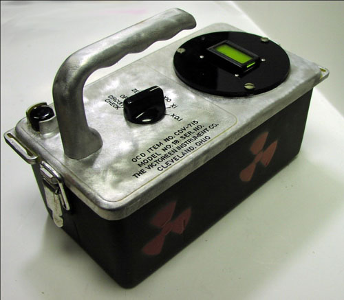
The CDV-715 has a perfect Cold War style case to house a modern sensitive digital Geiger counter, see figure 1. The Analog Digital meter displays Counts Per Second (CPS), Approximate Radiation Level in either imperial measurements (mR/hr) or metric measurements (mSv/hr). The top line of the display alternates every second between the approximate radiation level and the Counts Per Second (CPS). The 2nd LCD line is a power meter that provides a quick visual indication of the current CPS reading, more on this later, see figure 2.
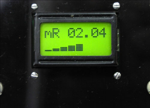
Figure 2 Analog-Digital Meter
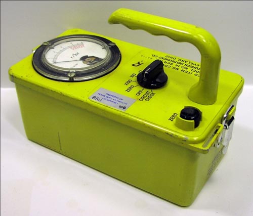
In the 1960's, at the height of the Cold War over half a million Civil Defense CDV-715 ion chamber radiological instruments were manufactured, see figure 3. In its day the CDV-715 could be found in government fallout shelters across the country. Unfortunately, this survey instrument only detects high levels of gamma radiation that would be encountered in a post nuclear attack or incident. So even good working CDV-715 models are not sensitive for most radioactive detection work.
Figure 3 CDV-715 Ion Chamber Radiological Instrument
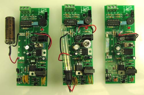
When FEMA decommissioned the CDV-715, the instruments made their way onto the surplus market. Since so many instruments were manufactured, and because of their lack of sensitivity the CDV-715 can be found on Ebay for low cost. If you would like to retrofit a sensitive Geiger Counter inside a Cold War style case, read on. First step purchase a surplus CDV-715 from Ebay or elsewhere. It doesn't matter if the CDV-715 is in working order or not. We will be gutting all the old electronics out. It doesn't require to have a meter either since that will be replaced with a new faceplate that holds the new Analog Digital Meter. In Make magazine 29, I wrote a construction article for a Geiger counter circuit that easily fits this application. While I will not repeat the construction details for the Geiger counter circuit, I will point out the retro-fitting details. I like this circuit because it lends itself to a number of GM tubes available on the market, see figure 4.
Figure 4 CGK-02 Geiger Counter Circuit Board with three different GM Tubes
So by using this Geiger counter circuit you can power any GM tube that requires either 400 or 500 VDC. The board is the same as the pc board in the original article with the addition of a mounting holes drilled into the pc board colored in red, see figure 5
Figure 5 Geiger Counter PCB mounting holes (red) and connections to Analog Digital Meter and external switch.
%20and%20connections%20to%20Analog%20Digital%20Meter%20and%20external%20switch.jpg)
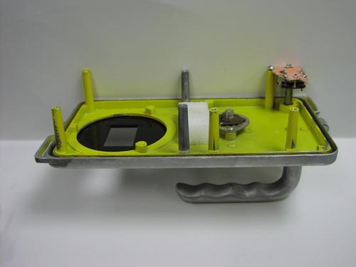
Place the pc board at the bottom of the CDV-715 case where you want to secure the pc board, see figure 6. Then use the holes in the PC board to mark the locations where you need to drill mounting holes for the 3/4" hex spacers to hold the PCB.
Figure 6 PCB in the bottom of CDV-715 case for marking mounting holes.
Do the same for drilling the holes for the 9V battery holder and GM Tube holder. The GM Tube holder I used was a 3/8" plastic cable holder. If I were using the LND712 GM tube I'd use a 1/2" plastic cable holder. Construct the Geiger counter board as per the instructions in the original article. There are a few minor changes are required You do not need the terminal block(s), the S1 switch or the speaker switch. The speaker switch should be jumped in the on position. (Alternatively, you could mount an external audio switch.) The S1 switch is replaced with an external rotary switch that is described in better detail later on in the retro-fitting section. You can solder two 9" wires in the S1 position for connecting the external switch. The terminal blocks are not needed, the pulse in wire from the Analog Digital meter is soldered directly into one of the "D" (digital output) pads used for the terminal blocks.
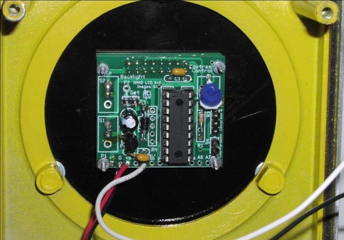
Figure 7 Analog Digital Meter (ADM)
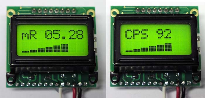
When I first thought of doing this project, I tried mounting my standard 16x2 character LCD. This LCD meter display was too large to fit into the space allocated for the front panel meter. So I designed a new PC board that uses a smaller 8x2 character LCD to create an Analog Digital Meter see figure 7. The 8x2 LCD fits nicely into the allocated meter space.
The smaller LCD presented new challenges regarding the display of information from the Geiger Counter. When using the 16 x 2 LCD display I had plenty of space to place the Count Per Second (CPS) on the top line and the equivalent radiation level in mR/hr (or mSv/hr) on the second line. In addition to this I wanted something that would replace an analog meter. I wasn't happy with the available analog meters or the electronics to implement them, so I decide to create my own.
The space allocated on the LCD's 8 character line doesn't permit me to write mR/hr, so I shorten this to mR. This left 5 characters to display the radiation level. I took a similar approach to displaying CPS. This left 4 character to display a CPS numerical value up to 9999, more than enough.
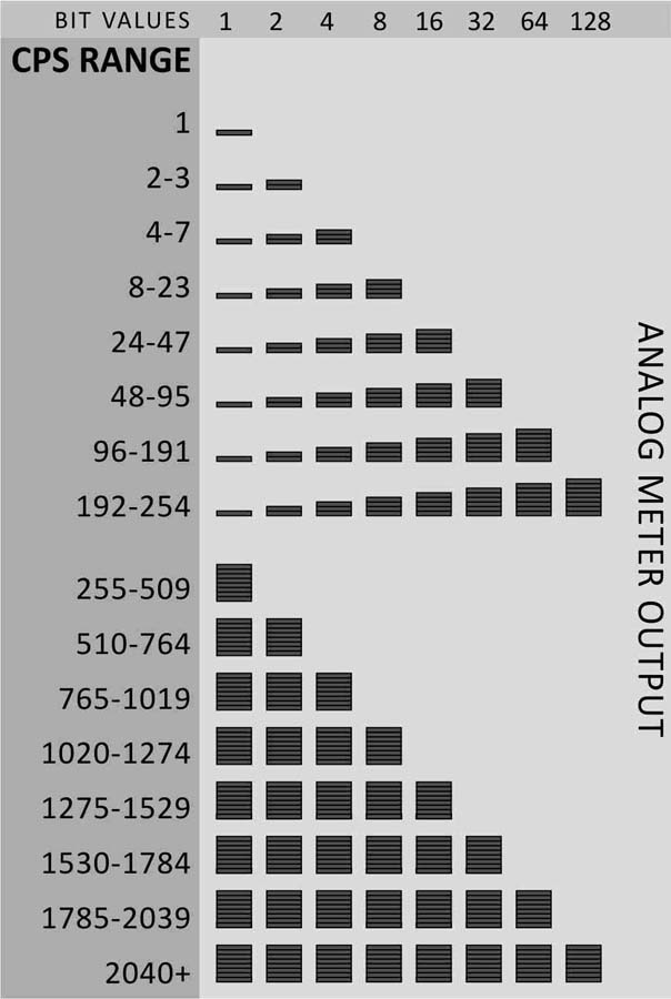
The second line of the 8x2 LCD is a dedicated analog power meter. To create the LCD analog meter I programmed 8 customer characters into the LCD. Each character represents a binary number: 1, 2, 4, 8, 16,32, 64 and 128. The chart below, see figure 8, provides an indication of how to read the power meter. Using the information we can obtain a reasonable approximation of CPS from 1 CPS to 2040 CPS from the second line of the Analog-Digital Meter. The chart below illustrates the CPS range capabilities of the ADM meter.
Figure 8 CPS range display chart for Analog Digital Meter.
Switching from Imperial to Metric Measurements
If one places a jumper on the two pin header on the back of the Analog Digital Meter, the display will change from imperial measurements mR/hr to metric measurements mSv/hr. The mSv/hr is shorten to mS to fit on the 8 character line. The CPS reading stays the same regardless whether meter is set for imperial or metric.
Building the 8x2 LCD display:
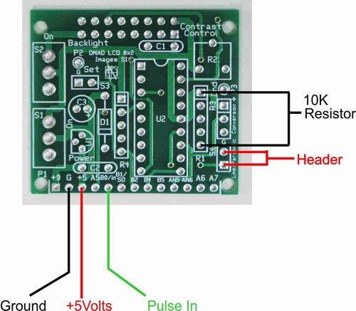
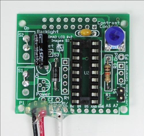
Because the LCD is connected to and powered by our main Geiger counter board, there are a few components we can eliminate from the pcb and simplify its construction. The power and backlight switches S1 and S2 are eliminated and replaced with a jumper. Since we are pulling 5 volt power from the Geiger Counter board, we can also eliminate the voltage regulator U1 and input capacitor C2 shown on the PCB. What's left is a spoonful of components to mount to get the 8x2 LCD Analog and Digital Meter working. Figure 9, is the Analog to Digital PCB for the 8x2 LCD.
Figure 9 Analog Digital PCB for the 8x2 LCD
Begin by soldering a wire jumper on S1 and S2. Mount and solder the 18-pin socket on the pcb, align the indentation on the socket with the indentation shown on the silk screen outline. Next mount the 10K resistor in position shown. Next solder two position header. Next mount and solder potentiometer in the R2 position. Mount and solder diode D1. Next mount and solder the .1 uF capacitor C1.
Figure 10 Mid construction photograph of the ADM pcb
Solder about 9 inches of 22 Gauge stranded wire to the ground pad, +5V pad and Pulse In pad. If you have color wire, use black, red and green wires respectively. At this point your ADM pcb should look like figure 10. All that is left is to solder the headers for mounting the LCD and inserting the pre-programmed chip into the IC socket.
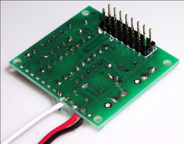
Flip the PCB over, mount and solder two 8-pin headers into the pcb, see figure 11.
Figure 11 Mount and Solder two 8-pin headers
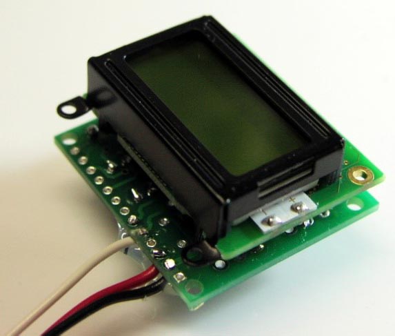
Next mount and solder the LCD to the 2x8 header pins, see figure 12.
Figure 12 Mount and solder LCD to header on ADM pc board.
Connecting the ADM to Geiger Counter Board.
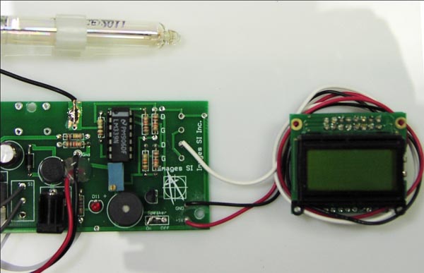
The GCK-02 board has a 5V output and ground pad, look back at figure 5. Connect the 9" length of red wire from the Analog Digital meter to the +5V pad on the Geiger counter board. Connect the 9" length of black wire from the Analog Digital meter to the ground pad on the Geiger counter board. Connect the 9" length of white wire from the Analog Digital meter to one of the "D" pads (digital output) on the Geiger counter board, see figure 5. The finished connection between the ADM and GCK-02 is shown in figure 13.
Figure 13 Analog Digital Meter connected to GCK-02 circuit board.
Preparing the CDV-715 Case and Power switch.
When you open the CDV-715 case it will resemble figure 14.
Figure 14 Open CDV-715 instrument.
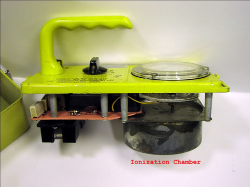
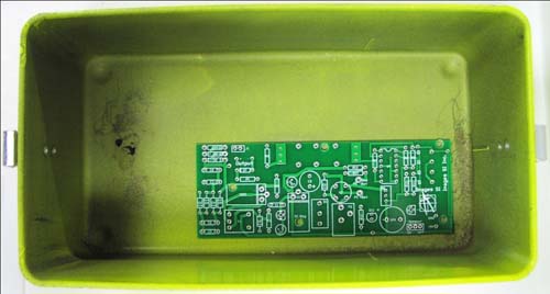
Remove, circuit board, ionization chamber and panel meter, see figure 15. Keep the screws for the panel meter. Going Further:
Figure 15 CDV-715 with circuit board, ion chamber and the meter removed.
The CDV-715 has a rotary power, the switch was integrated with the old PCB so its not useable for our circuit.
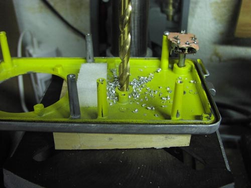
I wanted to keep a rotary switch in the same position for the retrofit to keep the overall look the same. I removed the old switch fixture and reamed the hole to 3/8" to accept the new switch. The thickness of the case prevented using the face plate nut to secure the switch. Rather than create a bracket for the rotary switch I glued the rotary switch into position.
Figure 16 Reaming existing hole to accept the new rotary switch
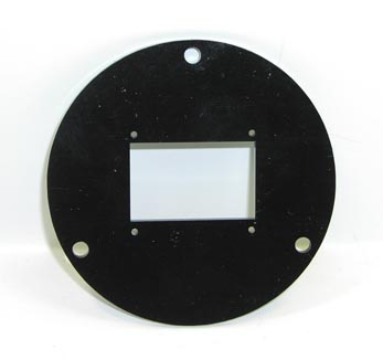
With the switch mounted it is time to begin assembling the unit together. The panel meter is replaced with a faceplate that has holes for mounting the Analog Digital Meter. The three holes along the circumference align with the screw holes in the case, see figure 17.
Figure 17 Laser cut panel meter to hold ADM
The Analog Digital meter is attached to the inside of the faceplate using four 0-80 machine screws and nuts, see figure 18. Figure 18 Analog Digital Meter secured to faceplate using 0-80 machine screws and nuts
In the final assembly attach the PC board to 3/4" hex standoffs using 4-40 nuts, the battery clip and the GM Tube to the inside of the CDV-715 Case, see figure 19.
Figure 19 Open enclosure view of finished retrofit circuit.
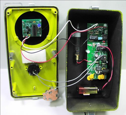
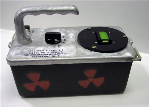
Figure 20 Finished Project
Here are a few things you can do to improve our Retrofit Geiger counter project.
One cut holes or louvers by the GM tube to improve the sensitivity of the GM Tube. The metal can of the enclosure blocks alpha radiation and attenuates beta radiation and gamma radiation. If one is using an Alpha Sensitive tube like the LND 712, you should drill a 1/2" hole in the case to allow the MICA window to see outside the case. A screen should cover this hole to help protect the sensitive mica window while still allowing it to see alpha radiation.
The GCK-02 Geiger counter PCB has an LED that flashes with each detected radioactive particle. This LED can be made external to the PCB and placed in the top cover of the case.
In the same manner the speaker can be extended and made external.
Parts List:
CDV-715 Ebay.com (see text)
Analog Digital Meter $45.55 http://www.imagesco.com/geiger/analog-radiation-meter.html
Front Faceplate ($6.00)
GCK-02 Kit $65.10 (no tube) http://www.imagesco.com/geiger/geiger-counter-kits.html
Misc:
Rotary Switch CKM9487-ND (Digi-key) or equivalent 9V battery holder
3/8-1/2" plastic cable clip to hold gm tube
br/>
(4) 3/4" Hex spacers
(4) 0-80 Machine screws 1" length
(4) 0-80 machine screw nuts.
Back To Table Of Contents