
This modified horn attaches to the base plastic part B using two 0-80 machine screws and nuts, as shown in figure 10. A ¾” long 6-32 machine screw is screwed into the 6-32 insert on the pen holder part A. The two halves of the pen holder are attached to one another using a male to male 6-32 hinged standoff. The standoff threads are coated with a permanent thread lock compound and screwed into the appropriate ends on parts A and B as shown in figure 11. The parts are screwed together so that both parts are lying in the same plane. The parts are left in this position allowing the thread lock to dry.
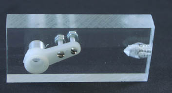
Figure 10
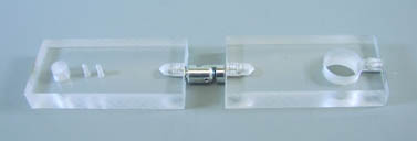
Figure 11
When the thread lock has dried, the penholder can be attached to the pen holder servomotor as shown in figure 12.
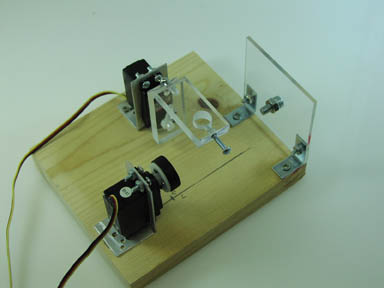
Figure 12