
For power I used a six AA battery pack holder with rechargeable NiCd batteries. The six batteries supply approximately 7.2 volts fully charged. The CMU camera is powered directly from the unregulated voltage from this battery package.
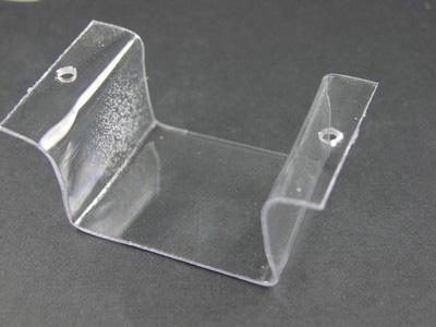
The battery pack is secured to the undercarriage of the platform using a molded piece of plastic, see figure 13. The battery pack fits inside the plastic and is secured to the platform using two 6-32 screws and nuts.
The entire circuit including the CMU camera has three power switches. I would recommend placing the CMU camera power switch in the ON position and using the main circuit board power switch to control power. The LCD also has a power switch. The LCD display is used in the Test Mode, and only in the beginning of the Run mode. The power switch allows you to turn off the LCD to conserve power.
Finishing the Assembly
With the battery pack attached to the body, all that remains is to secure the circuit board to the top of the robot’s body and we’re ready to go.
The CMU camera’s view of a target may be different then what you would expect. The C-Bot has two operational modes; TEST and RUN mode. The test mode has been designed to help you select good target objects and to test their functionality with the C-Bot robot. In test mode the servomotors are not active. The LCD display provides text information on what the CMU camera sees the target and how the robot would move if it’s servomotors were active.