
ESP/PSI Tester Project
Project Overview:
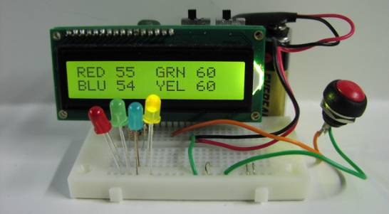
This project creates a random number generator using a simple momentary contact pushbutton switch.
How Random Numbers are generated
The way the momentary contact switch triggers and generates random numbers is best described by using a mechanical analogy. Imagine if you will numbers one to four painted on the edge of a revolving carnival wheel. There is a pointer at the top that indicates the number at the top of the wheel. The wheel is set into motion, spinning very rapidly, thousands of revolutions per second. Then at the moment the switch is pressed the wheel is instantl
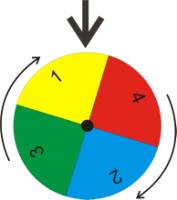 y stopped, and the number indicated under the pointer becomes our random number. Once the number is read, the wheel is set back into motion.
The microcontroller program in out ESP Tester follows pretty close to the mechanical analog. The microcontroller spins the sequence of numbers; 1 to 255, in a for-next loop. The switch press event instantly stops the for-next loop, and the current number of the for-next loop is read. The number is filter through a modulo 4 routine to bring the results into a 1-4 range. The results are displayed via the LCD display screen and LED’s. Then the program reenters the for-next.
You may ask the question, why not use a 1 to 4 for-next routine. The reason is this. We would be asking the microcontroller to stop every four iterations and reset the for-next loop. This finite amount of time is enough to throw the distribution off. Instead, we never check the number in the loop. once the "time" variable reaches 255 it automatically goes back to zero without any microcontroller program intervention.
We recommend pressing the switch approximately one time per second, so the ESP tester will produce approximately one random number every second.
ESP Tester Program
'ESP Tester - Random Number Generator using momentary contact switch
'(Human input as random physical quantity)
'Uses 16F88 with internal Oscillator
'Calculation by Reverse Modulo Adjust 1
'Range 1 to 4
'Random number generated is indicated by LEDs, shown on LCD
'Numbers 1 = Red, 2 = Blue, 3 = Green, 4 = Yellow
'Counting Variable isn't initialized to 0 on power up or reset.
'Input Switch on RB.0 pin
'RB7 connected to Red LED
'RB6 connected to Green LED
'RB5 connected to Blue LED
'RB4 connect to Yellow LED
'LCD connection, standard 4 - bit parallel PBP
'RA0-RA3 to LCD D4-D7
'RA4 to LCD RS
'RB3 to LCD Enable
'LCD R/W permanently grounded
#CONFIG
__config _CONFIG1,_INTRC_IO & _WDT_OFF & _PWRTE_ON & _MCLR_OFF & _LVP_OFF & _CP_OFF
#ENDCONFIG
define OSC 8 'define the oscillator frequency
IN var PORTB.0 'PORTB.0 as input switch
RBPU var OPTION_REG.bit7 'Port B internal pullup enable bit
w0 VAR WORD 'holds occurences for number 0
w1 var word 'holds occurences for number 1
w2 var word 'holds occurences for number 2
w3 var word 'holds occurences for number 3
time var byte 'counting variable
radm var BYTE 'holds current random number
modulo var byte 'holds modulo value for random number calculation
quotient var byte 'holds quotient value for random number calculation
OSCCON = %01110100 'Set-up internal oscillator at 8 Mhz
ANSEL = %00000000 'Set all I/Os as digital
PORTA = %00000000 'clear PORTA data latches
TRISA = %11100000 'make PORTA (LCD RA0-4 pins outputs)
PORTB = %00000000 'clear PORTB data latches
TRISB = %00000111 'make PORTB (LCD RB.3, )
RBPU = 0 'enable weak pull ups for PortB
w0 = 0 'initialize variables on power up
w1 = 0
w2 = 0
w3 = 0
Pause 1000 'pause for LCD initialization
LCDOut 254,1, "ESP Color Track" 'Display 1st line LCD
'LED runover on startup
lcdout 254,192,"RED"
PORTB = 128 'Red
pause 500
lcdout 254,192,"GREEN"
PORTB = 64 'Green
pause 500
lcdout 254,192,"BLUE " 'a space after BLUE
PORTB = 32 'Blue
pause 500
lcdout 254,192,"YELLOW"
PORTB = 16 'Yellow
pause 500
PORTB = 0
'Display template to show occurrences, only update occurences now
lcdout 254, 1, "RED", 254, 136, "GRN", 254, 192, "BLU", 254, 200, "YEL"
main: 'main counting loop
if IN = 0 then calculate 'if switch press detected
time = time + 1 'increment counting variable by 1
goto main 'go back to main loop for next increment cycle
calculate: 'calculation routine
modulo = time // 4 'calculate the modulo
quotient = time / 4 'calculate the quotient
if quotient.bit0 = 0 then 'perform reverse modulo,
radm = modulo 'if quotient is even, rn equals modulo
else
radm = 3 - modulo 'if quotient is odd, reverse
endif
PORTB = 0 'switch off previous LED's
Pause 200 'if new and old n are same, blink
if radm = 0 then 'update LED & LCD
PORTB = 128
w0 = w0 + 1
lcdout 254, 132, #w0
endif
if radm = 1 then
PORTB = 64
w1 = w1 + 1
lcdout 254, 140, #w1
endif
if radm = 2 then
PORTB = 32
w2 = w2 + 1
lcdout 254, 196, #w2
endif
if radm = 3 then
PORTB = 16
w3 = w3 + 1
lcdout 254, 204, #w3
endif
debounce:
if in = 0 then debounce 'wait if switch is still pressed
pause 20 'debounce key depress
goto main