
Wheel Construction:
We finish up this article with a method to make simple servomotor wheels. We start with a 2” diameter hard wood dowel. We cut 3/8” thick disks from the dowel.
 |
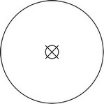 |
Figure 25 |
Figure 26 |
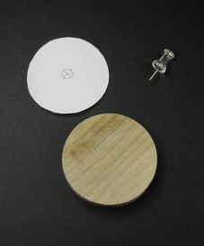
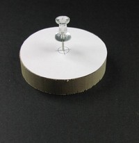
Figure 25 illustrates one wood disk, paper guide (figure 26) and a push pin to mark the disk. The guide is aligned onto the wood disk. The push pin is pushed through the paper making the exact center of the disk, as shown in figure 27.
 |
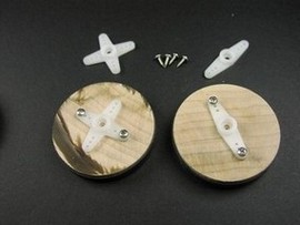 |
Figure 27 |
Figure 28 |
Remove the paper and push pin from the wood disk. Next align a servomotor horn onto the wood disk. Align the push pin hole to the center of the center screw hole on the servomotor horn. Attach the aligned servomotor horn to the wood disk using #4 x ¼” long sheet metal screws, see figure 28.
Optional steps:
1) File flat the side of the servomotor horn that touches the wood disk.
2) After servomotor horn is attached, remove the horn to drill a ¼” hole through the center of the wood disk. Next reattach the servomotor horn. The drilled hole allows you to attach the wheel to the servomotor using the horn screw.
Parts List:
- CMU-01 Camera
- Plastic Body (see text)
- (2) Continuous rotation servomotors
- (1) HS-322 HiTec servomotor or equivalent
- (2) servomotor wheels
- (1) Caster wheel, with ¼-20 screw and coupling
- LCD display module
- 16F628 PIC Microcontroller
- 16 MHz Xtal
- (2) 22pf capacitors
- 7805 Voltage regulator
- 7806 Voltage regulator
- Battery pack (6-AA batteries)
- (3) 220 uf 16V capacitors
- (3) 10K ¼ watt resistors
- 4.7K ¼ watt resistor
- 33 ohm ¼ resistor
- 20K potentiometer
- MISC switches, plastic, 6 AA battery holder, 6-32 machine screws, nuts and #6 lock washers.