
The optimum duty cycle and frequency for the strobe photoperiod needs to be determined. In other words we're flying blind in regard to optimum frequency and duty cycle. The circuit I designed is 3Hz with a 50% duty cycle. I chose this frequency based upon using a convenient 1-uF capacitor, for a 555 timer IC. The schematic is shown in figure 2 (below).
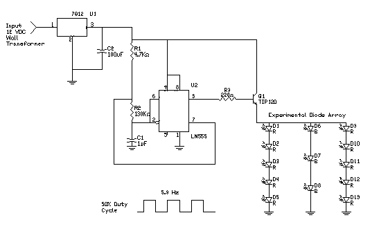
The output from the 555 timer (pin 3) is connected to the base of NPN Darlington Transistor (TIP120) T1. The NPN transistor switches the current on and off to the strobe LED lighting module.
There is a voltage drop across the collector-emmiter of the TIP 120 transistor. To insure the equal brightness from both the LED modules, I place a dummy TIP120 transistor, T2, in line with the control LED module (see figure 3, below). The transistor T2 matches the voltage drop across T1 to help supply an equal voltage to the control LED modules.
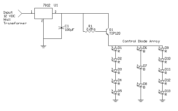
The T2 transistor is kept forward bias (always on), when power is applied through resistor R4 (2.2K ohm). The voltage drop I measured across the TIP120 transistors is approximately 1.5 volts.
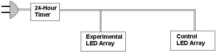
An overall view is shown in figure 4 (above). A 12 VDC wall transformer powers the circuit. The wall transformer is plugged into an inexpensive Radio-Shack AC appliance timer set for a 12 hour on period. The wall transformer supplies voltage to both circuits.
Previous Page (Photosynthesis Graph) | Next Page (LED Lighting Module)