
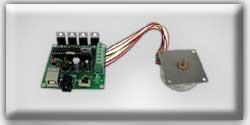
 USB Stepper Motor Kit
|
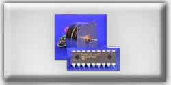 PIC Stepper Motor Kit
|
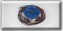 Stepper Motor
|
By using an external stepper motor controller, such as the UCN 5804, you can simplify your programs and control as many motors as you have outputs via an array of UCN 5804's. Not only does it allow for the control of more motors, but more importantly, it simplifies the process. You now only have to output the pulse of your desired speed. Additionally, you can switch between full and half stepping in real time via a switch on the UCN 5804 (or you may have the PIC control it), as well as reverse direction. A pinout for the UCN804 is shown in Figure 8.
The schematic we will build to use this chip is shown in Figure 9. Since we are using a 5V stepper motor, we will be powering the UCN 5804 with a 9V wall transformer. You cannot use 6V, due to the draw of the motor. The UCN 5804 can support voltages up to 35V.
Notice in the schematic that two resistors, rx and ry, do not have an assigned value. This is because our motor draws only 100 mA, well under the chip's supported 1,250 mA. However, if you were to use a motor that draws the maximum or above, then you would need to use rx and ry to get the amperage under 1,250 mA. For example, a 24V motor with a phase resistance of 15 ohms would draw 1,600 mA (24/15 = 1.6). In this case, you should use _at least_ a 5 ohm resistor for both rx and ry, which would bring the current down to 1.2 A.
Since the input of the UCN 5804 is CMOS and TTL compatible, we can connect the outputs from the PIC directly into the UCN 5804. Two outputs are needed; one to control the step input (pin 11), and one to control the output enable (pin 15) which enables the stepper motor while high and disables the stepper motor while low.
Pins 9 and 10 control the stepping method (half or full steps). Pin 14 controls the step direction. Both of these controls can be manipulated by the PIC, but it is easier to control them directly through the use of jumpers acting as switches.
All the program has to do, is output a pulse and set the output enable low. This can be accomplished with a very simple program such as the following:
Listing 3
' Stepper motor control with a UCN 5804
Symbol delay = B0
low 1
delay = 10
delay = delay * 1000
loop: pulsout 0,delay
goto loop
' make a delay variable
' set the output enable low
' set a pulsewidth of 10 ms
' turn delay into microseconds
' send pulsewidth of delay to UCN5804
' repeat forever
End Listing 3
Notice that I added an extra step; taking the defined "delay" value and multiplying it by 1,000. This is necessary because the pulsout command requires a pulsewidth in micro-seconds, not milli-seconds. You can make the code even smaller by removing lines 1, 3, and 4 and replacing "delay" in line 5 with a set number in microseconds. However, I prefer to the method shown in the listing, because it makes it easier to change the delay parameter in the more familiar milliseconds without having to convert it to microseconds.