
Circuit Assembly
The schematic is shown in figure 10. The circuit can be hardwire onto a breadboard or you can purchase a pc board, see figure 11. The LCD display used is a 2 line by 16 character display. You can use an LCD module with a Hitachi 44780 controller or equivalent. These LCD’s usually have a 14 or 16 pin header.
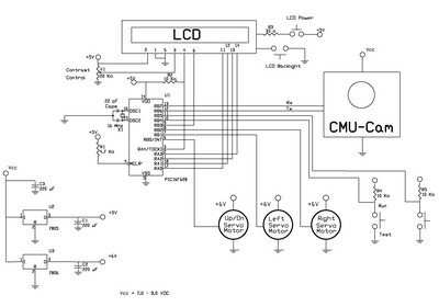
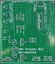
Figure 10
Figure 11
We need to set one jumper on the camera and connect four wires from our circuit to the CMU camera.
Look at figure 12. Place a jumper on jumper position 2. This sets the camera baud rate to 38,400. The power is supplied to the two header positions shown on figure 12, as well as the header positions for the serial transmit and receiver lines.
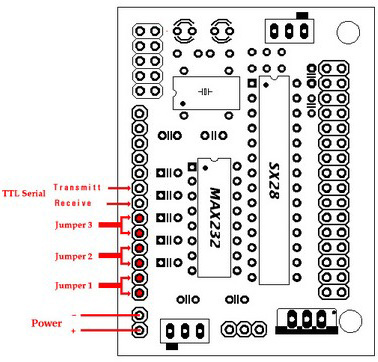
Figure 12