The Circuit:
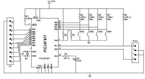
The circuit is based on the PIC 16F877 microcontroller, see schematic in figure 4. The digital display output of the speech recognition circuit connects directly to the pins of the microcontroller. The LED in, provides a trigger that informs the microcontroller when a word has been spoken. The LED output connects to one side of a comparator. The other side connects to a voltage divider (Vref) made up of resistors R2 and R3 creating a reference voltage for the comparator. When the LED blinks on the speech recognition circuit it triggers the 16F877 microcontroller on the X-10 interface that a word has been spoken. The microcontroller then reads the digital display output to determine if the word has been recognized (target word) or non-recognized (error code). If it reads a target word number it transmits the appropriate command and house code to the PL513 Power Line Interface.
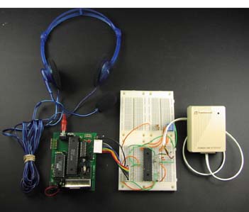
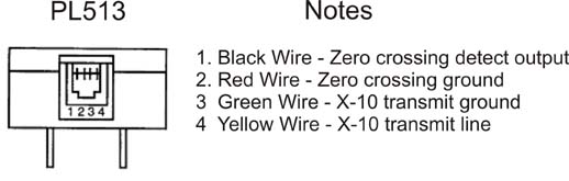
The X-10 circuit board connects to the PL-513 using a short 4-conductor
telephone line, see figure below.
Building the Circuit
The next figure shows my prototyped circuit I build on solderless breadboards. Nothing is critical about the circuit, you can use point to point wiring on standard breadboards if you like.
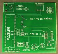
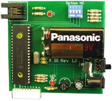
The pc board and circuit is also available as a kit through my company, Images Scientific Instruments Inc., see parts list. The pc board is shown below. The kit eliminates wiring error and provides a finished appearance.