
While this particular robot doesn't incorporate the electronics for an on board power supply, it still uses a light trigger. The circuit shown in figure 1 controls the power from the batteries to the gear box motor. The circuit reads the level of illumination that the robot sees. If the light level is high enough it turns on the motor to the gear box. The trip level of the circuit is user adjustable using potentiometer V1.
Gear Box:
Before we get into the construction of the robot, lets first look at the gear box. There are two gear boxes available, see figure 2.
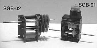
Figure 2
The gearbox labeled SGB-01 must be assembled. This gear box has a slide switch that one can use to easily change the gear ratio. The gear ratios of this box range from 6.8:1 to 808:1. The height of the gear box makes it a tight fit in the transparent sphere. If you decide to use this gear box when assembling the unit set the gears to the highest ratio available (808:1). This is the gear box used in the prototype.
The gearbox label SGB-02 comes fully assembled. Physically this gearbox is shorter than the SGB-01 and is easier to fit inside the sphere. It has a 4000:1 gear ratio. The gear ratio may be change but that requires you disassemble the unit. If I were building this robot again I would choose this gear box. First for its physically smaller size and second for the higher gear ratio. The higher gear ratio will make the robot move slower.
In the prototype, even though I have the SGB-01 gear box set to the 808:1 ratio, the robot still travels just a little too fast. I would prefer it to go slower.
Robot Construction:
The shell is the first component for consideration. It must be transparent and large enough to hold the gear box and electronics. The shell used in my prototype has a diameter of 5 1/2 inches. If you can not find a suitable shell locally, you can purchase one from Images Company, see suppliers list. The plastic shell is fragile. Do not have your robot try to climb or fall down stairs; it is sure to crack and break.
Separate the two halves of the shell. The first job is to locate the center of the half sphere. This is where we will connect the shafts of the gear box. Locating the center at first appears much easier than it actually is. To find the center I was forced to trace the diameter of the shell on white paper. Then draw a box around the drawn circle that touched the circle on four sides. Drawing diagonal lines from the corners of the box I was able to locate the circle center. The half sphere is then positioned where you may be able to eyeball the center and mark it on the sphere with a magic marker. I tried once or twice with less than ideal results. Finally, I taped the paper on a 1/2" piece of wood and drilled a small hole at dead center. Then I placed a small dowel, about 2.5" long in the hole, making sure it was perpendicular to the wood. Place the half sphere over the fixture, lining up its diameter with the drawn circle, the dowel locates the center of the sphere fairly accurately. Mark the center of one half sphere then the other.