
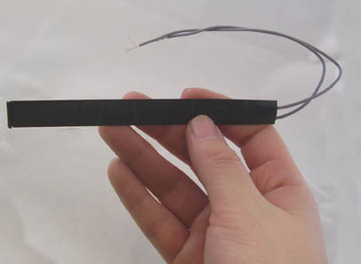
Flex sensors are passive resistive devices that can be used to detect bending or flexing. The flex sensor shown in this article is a bi-directional flex sensor that decreases its resistance in proportion to the amount it is bent in either direction. The sensor we are building is about 3/8" wide by 5" long. You can easily make a sensor wider and longer depending upon your application:
Applications
Flex sensors may be used in robotics to determine joint movement or placement. They may also be used like whiskers for wall
detection. The sensors we are making are also pressure sensitive so they can also be used as bumper switches for wall
detection or pressure switches on robotic grippers.
For bio-metrics, the sensor can be placed on a moving joint of athletic equipment to provide an electrical indication of
movement or placement. A few of the sensors can be incorporated onto a glove to make virtual reality glove.
Components:
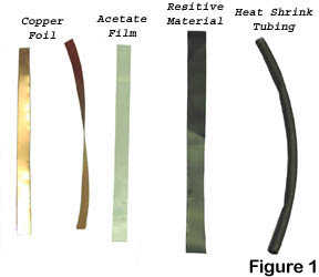 The materials needed for the construction of the bi-direction flex sensor is shown in figure 1 and listed below. The size
of the materials listed is only a guideline to the sensor we are constructing in this article. These types of sensors can
be manufactured to larger widths and lengths.
The materials needed for the construction of the bi-direction flex sensor is shown in figure 1 and listed below. The size
of the materials listed is only a guideline to the sensor we are constructing in this article. These types of sensors can
be manufactured to larger widths and lengths.
- Copper foil laminate ¼" x 4.5" (see text)
- Acetate ¼" x 4.5" x .010 thick
- Heat shrink tubing 3/8" dia x 5"
- Resistive material 5/16" x 5" (see text)
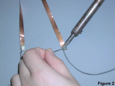
Copper foil laminate is used in the electronics industry to make flexible circuits. It is thin copper cladding on a plastic material substrate like acetate. The material we are using is single sided copper. Copper on one side and the substrate (plastic) on the other, The copper cladding material is cut into two pieces ¼" wide x 4.5" long strips. The material is easily cut with a scissors. Solder about 6" of wire to one end of each strip. You may fine it easier to solder the wire to the strip if you tin the bottom 3/8" of each strip. Solder each wire to one corner side of the strip. It doesn’t matter which side you choose, just make sure you solder both strips on the same side, see figure 2.
Resistive Materials
There are a variety of resistive materials available; cloth, plastic and paper. The common element of all the appropriate
materials is that the material is somewhat conductive or resistive. The degree to which the material is resistive will
determine the scale at which your flex sensor operates.
For the example here I am constructing here, I using conductive black plastic poly bags conductive bags used in the
electrical industry. These bags are used to store components that are static sensitive. The bags are made from single layer
of carbon-loaded polyethylene and its conductivity does not depend on humidity. I cut the bags into the 3/8
" wide by 5" long strips.
Making the Bi-Directional Flex Sensor:
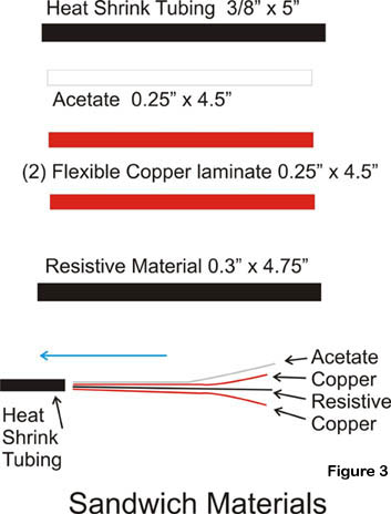
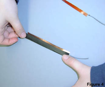
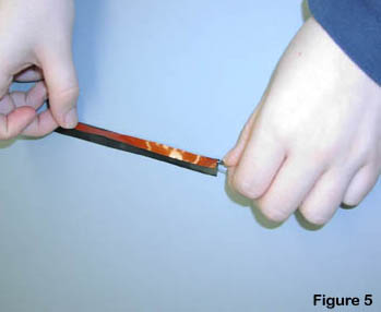
The resistive material is sandwiched between the two copper clad laminates.
The copper sides of the laminates are both facing toward the resistive
material; see figures 3, 4 and 5. If you soldered the wires on the same
side of the laminates, when you assemble the sensor, the wires will
be positioned on opposite corners allowing the base of the sensor to
lay flatter.
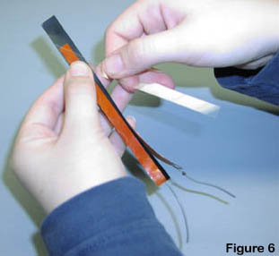
To this sandwhich we add the acetate strip, see figure 6. The purpose
of the acetate strip is to make the sensor more resilient and to spring
back after it has been flexed.
Making the Bi-Directional Flex Sensor:
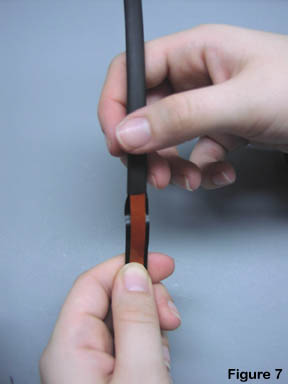
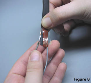
This entire sandwich is inserted into the heat shrink tubing, see figure 7. The base of the sandwiched materials is shown in figure 8, just before it is inserted completely into the heat shrink tubing.
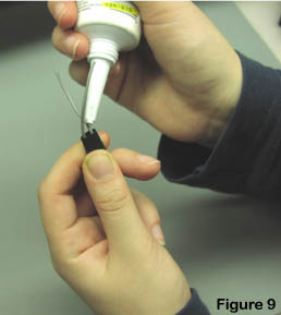
You are almost finished. At each end of the heat shrink tubing place a small amount of clear silicon sealer, see figure 9. Allow the sealer to dry according to its directions, usually around twenty-four hours.
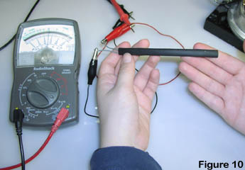
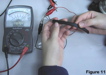
Testing the Bi-Directional Flex Sensor:
Set a VOM meter to read ohms. The sensor we built had a nominal resistance
of approximately 20K ohms, see figure 10. As the sensor is bent in one direction
 the resistance decrease in proportion to the bend to approximately 2k, see
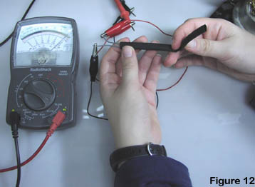
figure 11. Bending the sensor in the opposite direction also decreases the
resistance in proportion to the bend to 2K ohm, see figure 12.
the resistance decrease in proportion to the bend to approximately 2k, see
figure 11. Bending the sensor in the opposite direction also decreases the
resistance in proportion to the bend to 2K ohm, see figure 12.
The sensor is also pressure and force sensitive. So pressing down on
the sensor will also decrease it resistance.
The basic sensor can be modified in size and shape to fit custom applications.
The resistive material may also be modified to obtain different resistances
and characteristics. Most materials are easily obtained from electronic sources.
Images will supply the following materials to get you started. Flex Sensor
Components