The electronic circuit is not critical. You can construct the circuit using point to point soldering on a proto-typing bread board. Once the circuit is complete you need to adjust the light level that will activate the circuit using potentiometer V1. Make temporary connections to the gear box motor using alligator clip wires. Power to the circuit and gear box is obtain from two AA cells. The AA cell pack is glued to the back of the gear box during final assembly. Make sure the battery pack has a battery clip for easily disconnecting and connecting power.
When making the light level adjustment use a low level of light to activate the robot. When the robot is on the floor, if the light level is set too high it will stop every time it passes under a shadow.
Putting it all Together:
Once the circuit is adjusted you are ready for the final assembly. Glue the AA battery pack to the back of the gear box. Making sure that no glue comes into contact with any of the gears. The electronic circuit board is glued to the front of the gear box. Again, making sure none of the glue touches any of the gears. Connect the power supply. At this point the gear box will probably start turning. To load the mechanism inside the robot, bring all the parts into a dark room to deactivate the circuit. Load the assembly inside the sphere.
Take the robot out into the light. The gear box should become active. Place the robot on the floor. The robot should travel toward or in the direction of light. If the robot does the pposite, stop the robot, remove the gear box and electronics, and reverse the wires leading to the motor.
Locomotion:
I was pleasantly surprised when I began observing this robot. I originally thought it would become trapped easily. Not so. When the robot enters a corner and stops, the gear box inside begins swinging all the way up and over radically shifting its weight over top dead center and moving the robot out of the corner.
Advancing the Design
When I originally designed this robot I planned to use a steering mechanism to track a light source. However the small steering mechanism didn't have enough weight to turn the robot in any direction quickly. In the long run other factors (terrain, obstacles, etc.) affect its direction. Hence I removed the steering. But this is still a good research area for advancing the overall design.
Adding Higher Behavior Module
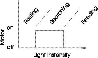
As the robot stands, when a certain level of light is reached it becomes active. We can add a higher behavior mode, feeding, by adding a few more components (two solar cells and steering diodes) and another comparator circuit. The second comparator circuit will deactive the motor when the light illumination level becomes high enough. Allowing the solar cells to charge the AA batteries which will be changed to Nicads. Figure 5 illustrates the behavior. When the light level is low the robot is off or we can say it is in a resting mode. As illumination increases it reaches a point where the motor turns on, the robot enters its searching mode. When the light level increases significantly beyond this point (searching mode) the second comparator turns off power to the gear box motor, allowing the two solar cells to charge the AA Nicad batteries, or the feeding mode.

Figure 5
If anyone plans to add this feeding behavior circuit, keep track of the current drain to the comparator circuits. It must not exceed the current supplied by the solar cells or obviously no charging to the Nicads will occur. If you would like to see this behavior added to the robot contact me through this magazine.
Parts List
(1) 5 1/2" Transparent Plastic Globe
(1) Gear Box SGB-01 or SGB-02
(1) 6" length of 1/2" solid plastic rod
(1) 3" length 5/8" OD 1/2" ID Plastic Tubing
(1) 1" length 1/2" half round plastic rod
Electronics
(1) CMOS Op-Amp ALD 1702 or equiv.
(2) 33K ohm 1/4 watt resistor
(1) CdS Photoresistor
(1) 4.7K ohm potentiometer (PC mount)
(1) 15K ohm resistor
(1) .0047 uF capacitor
(1) Tip120 NPN darlington
(1) PC board

