What is Kirlian Photography?
Kirlian photography is a high voltage, contact print photography.
Kirlian photography is named after Semyon Davidovich Kirlian and his wife Valentina who began their work with high voltage photography in 1939. Kirlian collaborated with his wife for over 30 years developing equipment and studying electro-photography.
Kirlian's work was first made known to the general public in this country by a book published in 1970 by Shelia Ostrander and Lynn Schroeder titled "Psychic discoveries Behind the Iron Curtain". Kirlian work became so well know that the field of high voltage electro-photography is called Kirlian Photography.
Although Kirlian wasn't the first to study electro-photography. The field of electro-photography can be traced back to the late 1700s. At this time Georg Christoph Lictenberg noted the pictures made in dust create by static electricity and electric sparks. Nicola Tesla (1880) photographed many corona discharges using his famous Tesla coil. In the early 1900s, Russian researcher Yakov Narkevich-Todka exhibited electro photographs he had made. A little later, Dr. F.F. Strong of Tufts University Medical School used a Tesla coil to make electro-photographs of his hand.
Making Kirlian Photographs
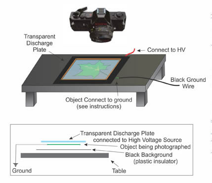
The process is simple. Sheet film is placed on top of a metal plate, called the discharge or film plate. The object to photograph is placed on top of the film. If the object to be Kirlian photographed is inanimate, such as a coin or leaf, a earth ground is connected to the object. See figure 1 below. High voltage is applied to the plate momentarily to make an exposure. The corona discharge between the object and discharge plate passes through and is recorded onto the film. When the film is developed you have a Kirlian photograph of the object.
The Kirlian process, being a contact print process, doesn't require the use of a camera or lens. However when a transparent electrode is substituted for the discharge plate it is possible to use a standard camera (with a bulb setting) or video camera.
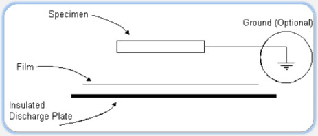
Figure 1
Paranormal Claims
I was first introduced to Kirlian photography, by the book titled "Psychic Discoveries Behind the Iron Curtain" by Shelia Ostrander and Lynn Schroeder in the early 1970's. In it many paranormal claims were made concerning the resulting Kirlian images. For instances, it was said that the Kirlian photograph could foretell illness in plants and animals before physical manifestations of the disease became apparent. I have experimented with Kirlian photography over the years. I have not observed any "paranormal" evidence of this phenomena.
One must keep in mind that most observable Kirlian phenomena does not require any paranormal or bio-plasma field to be explained. For instance, stress or the "act of lying" can easily be detected with a lie detector that relies on measuring the change in a person's galvanic skin resistance. Stress may also be seen in a Kirlian photograph as a change in the corona discharge (aura), however this change is easily explained by the change in a person's skin resistance without the need of evoking any metaphysical properties.
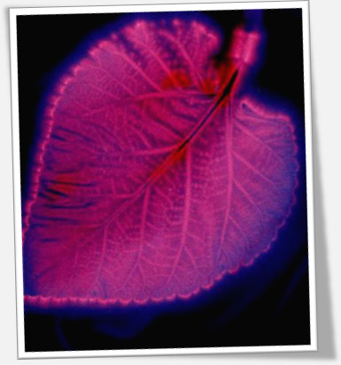
The Phantom Leaf Experiment
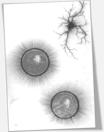
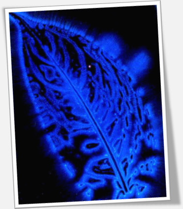
The one observed phenomena and, the most amazing claim (in my opinion) is known as the "phantom leaf" experiment. Here a small portion of a leaf is cut off; the leaf is then photographed using Kirlian photography. In a small percentage of cases the cut portion of the leaf appears in the photograph as a ghostly apparition. The appearance of the cut portion of the leaf, as claimed by the Soviet researchers is proof of an ethereal bio-plasma body.
Although a few Kirlian researchers have claimed to duplicate the phantom leaf experiment in their own labs, the most reported successful results (phantom leaf photographs) are from Soviet researchers. The exact experimental parameters (voltage, frequency, etc) needed to obtain phantom leafs are either not available or didn't work for me.
Kirlian Photography Devices for Sale on the Internet
There are Kirlian devices being sold on the internet today. To sell their devices the corona discharge in the resulting kirlian photograph is claimed to be paranormal or hold information that can be decrypted by the company's Kirlian researchers. All my research to date shows the corona discharge can be explained by employing known physical laws, like changes in subjects skin resistance (due to factors like; stress-lying, illness, fatigue, alcohol consumption, etc) without the necessity of invoking paranormal (bio-plasma) factors. Some other variable factors influencing the resulting Kirlian picture including the object's pressure against film, air humidity, air pressure, voltage, frequency, and exposure time.
This company also sells Kirlian devices and components, but we do not make any "paranormal" claims to try to sell our devices. Our devices are sold to make brilliant Kirlian photographs. If one wants to do research with our devices that fine also. Just know we make no claim that any interpretation of the corona discharge is due to anything other than standard variable physical parameters as outlined previously.
Building a basic manual Kirlian device
The next page we will begin the construction of a simple manual kirlian device. This device uses a battery power supply, high voltage ignition coild, copper clad board and a handful of components.
Building a Simple Kirlian Photography Device
The Kirlian device we are building uses a HV transformer. It is battery powered, but don't let that lull you into a false sense of safety. The Kirlian device generates pulses of high voltage that can provide a nasty shock. Still an advantage of being battery powered is portability.
In addition we will build a transparent electrode that allows one to use a standard camera (with bulb setting) to capture Kirlian images.
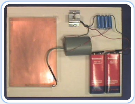
The schematic is shown in Figure 2. A completed circuit can be seen below the schematic. This is a simple manual device. It uses very few components. You would be hard pressed to find a simpler device that works as well. The prototype is built on a single piece of wood measuring *" x 10" x �" thick (see photo). The batteries B1 and B2 are 67.5-volt photo (instrument) batteries wired in series to produce 135 volts.
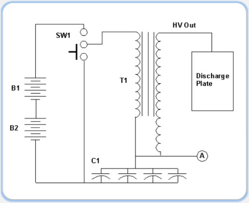
Figure 2
If the photo batteries are not available you may want to try wiring 10 or more 9-volt batteries in series. The discharge will not be as intense, but it will work. Another option is to take the output from a 120V/24V step down transformer connected to a voltage quadrupler. With the 24V (AC) output wired to a voltage multiplier (4x), the unit should produce about 100 volts that can be used for the power supply for this Kirlian device.
The capacitors C1-C4 are wired in parallel as shown in Figure 2.
The transformer T1 is a high voltage auto-transformer. Auto as in self-inductive, not auto, like automobile. The T1 transformer has three wires coming out of it: two enamel wires and one green insulated wire from the center. The green insulated wire is the high voltage wire that connects to the discharge plate. The two enamel wires are the primary wires that are connected to switch SW1. There is no polarity with the enamel wires. So it doesn't matter which enamel wire is connected to the switch, and which is connected to the capacitors. Either way the circuit will function properly.
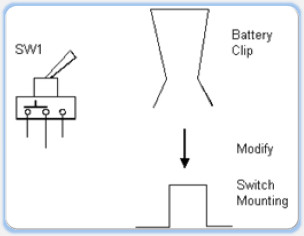
Figure 3
The toggle switch SW1 is a single pole double throw "momentary" contact. The switch has solder wires on the bottom, see Figure 3. This particular switch doesn't lock or stay in the opposite position. A built in spring immediately brings the switch back to its original position. To operate the device, toggle the switch on and off. When the switch is in the "on" position, it closes a current path to the HV transformer and capacitor bank.
The switch is important and must be wired correctly to obtain maximum benefit. Looking at the schematic shows how the switch appears in its resting state. In the resting state the batteries are disconnected from the circuit. This preserves the life of the batteries. Also the discharge path from the capacitors is closed. This prevents a potential shock hazard from being stored in the capacitors, to be unleashed on an unsuspecting experimenter.
To mount the switch to the board a metal battery clip (9-volt) is used, see parts list. The clip is bent to make a U shape as shown in Figure 3. The center hole in the clip is enlarged to fit the switch SW1. A hole is drilled in each ear of the clip to secure it to the board with two wood screws. The switch is secured to the clip, and then the assembly is secured to the board.
Exposure Plate
The exposure (or discharge) plate is made from 4" x 6" single sided copper clad board. The high voltage output wire (green) from transformer T1 is soldered to the corner of the copper clad board. The copper side of the board is placed face up and glued to the wood board.
After the glue dries, the discharge plate is covered with a thin plastic sheet approximately .005 inch thick. The plastic should extend at least 1" past the discharge plate on all sides. The sheet is secured in place by taping or gluing it down.
The thickness of the plastic sheet isn't critical. Anything around this thickness that will prevent the object from making direct contact with the discharge plate. Sheets are available from many art and drafting supply stores. The plastic sheet may be transparent or opaque, it doesn't matter.
To test the circuit, attach a wire to point A shown on the schematic and place the other wire about ¼" away from the discharge plate or the uninsulated end of the high voltage wire. Note the discharge plate should not have the plastic sheet covering it during the test. Every time you flick the switch SW1 you should see a spark jump from the HV wire to the discharge plate.
When the circuit checks out properly, mount the components on the board using glue or epoxy.
Coat any exposed wires with a plastic spray to provide insulation (No-Arc spray is available at your local Radio-Shack stores.)
Cover discharge plate with plastic sheet.
Sheet film used for Kirlian Photography
Black & White Film
Kodalith 2556 Ortho film type 3 is a high contrast B/W graphics arts film available in a 4" x 5" sheets. This film is perfect for beginners because you can use a red safelight and not work in complete darkness. If a safelight isn't readily available you can try using a red LED, neon lamp or wrap red acetate plastic over a dim 4 watt bulb.
I advise all beginners to start with black and white ortho film. It is less costly and easier to work with than color sheet film. You also have the opportunity to develop the film to get immediate feedback. Someone who starts off shooting color film must wait to get the film develop to see what has been recorded.
Developing B/W ortho film is easy. The chemistry works quickly and is simple and forgiving. You only need two chemicals; developer and fixer. A stop bath is usually employed in between these two steps, but isn't absolutely necessary.
Black and White (film or prints) is not as spectacular as color. The experience one gains by being able to observe all the steps under a safelight is invaluable when one has to work in complete darkness with color film. Using a high voltage power supply in the dark can be a pretty daunting task, so it's best to familiarize yourself with the process in the least costly manner.
Color Film – Daylight or Tungsten Balance
Color film requires exposures to be made in total darkness. Working in total darkness can be a problem. Sometimes I sandwich the color film between two black opaque sheets of paper in total darkness, then turn on the safelight. After I make my exposure, I turn off the safelight and place the film in a light tight box for development in total darkness.
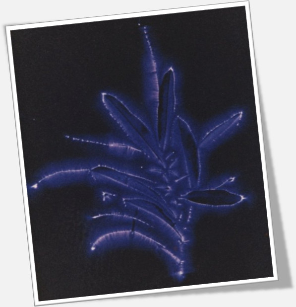
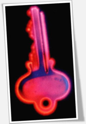
Both tungsten balance and daylight film give striking color transparencies. The tungsten balance film usually produces colors in the yellows, oranges and reds. Daylight film usually produces colors in the blues and greens.
|
 |
Daylight Type Sheet Film |
Tungsten Balanced Sheet Film |
Making Exposures Using Sheet Film
What you are photographing determines whether or not the object involved should be grounded.

Whenever you photograph a living subject (person, animal or pet) under no circumstances should that subject be grounded or be allowed to touch a ground during exposure. Being in contact with a ground will lead to a nasty shock. Further, anyone with a heart condition or pacemaker should consult with their primary care physician before photographing or allowing themselves to be photographed using this Kirlian device.
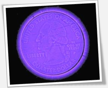
When photographing an inanimate object such as a coin, keys, leaf, etc. then connect a ground to the object. Grounding the object produces a stronger corona discharge. You can use a natural ground by connecting a wire to an earth ground, such as a cold water pipe. Or you can use a circuit ground by connecting a wire to point B (see Figure 2) to the object.
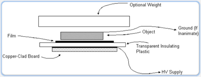
Figure 4
Figure 4 illustrates the overview for making an exposure. In some cases you might place a flat sheet of glass (or plastic) on top of the object to make the object lay flat on the film and discharge plate.
Whether you're working with black and white or color film, place the film emulsion side up on the discharge plate. Place the object you are photographing on top of the film. If the object is inanimate, connect a ground wire to it. Flick the switch SW1 about 10-20 times. Each time the switch is flicked you should see a discharge between the object and the discharge plate. This is what is being recorded on the film. Proper exposure is determined by trial and error, making adjustments accordingly.
Often times one uses B/W sheet film to determine the proper exposure then switch to a color sheet film for the final shoot. Black and White ortho has the advantages of being able to work using a red safe light and easily developed.
If you would like to use a standard 35mm camera or video camera to record Kirlian pictures it is possible, but you need to construct a transparent electrode.
The 35mm camera should be a single lens reflex (SLR) type with one or two close-up (macro) lens. In addition the camera needs to have a Bulb (B) setting on its shutter speeds. The B setting keeps the shutter open for as long as the shutter is held down.
Photographers typically use a cable release connected to the shutter to make B exposures. Most cable releases can be set to keep the shutter close when first pressed. The cable has a release mechanism the photographer hits to release the cable and allow the shutter to close after the exposure is made.
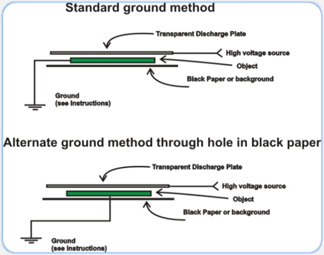
Kirlian Photography using a Transparent Discharge Plate
To take Kirlian photographs using a standard 35mm film camera, digital camera or video camera, requires the use of a transparent discharge plate.
To shoot Kirlian Photographs using a transparent discharge plate, the object is placed on one side and the camera on the other. The high voltage is applied to the transparent discharge plate and the camera shoots through the transparent discharge to capture the corona discharge around the object, see figure 5 below.
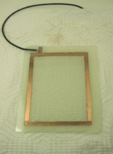
A transparent discharge plate is constructed from three main components; a 4" x 5" piece of glass that has a transparent conductive coating (typically tin oxide) on one side, see parts list, a ring electrode made from thin copper sheeting or thin one sided copper clad board, and a .005 thick piece of transparent plastic. The transparency of our transparent discharge plates surpasses 90 percent.
The conductive tin oxide coating on the glass is delicate. The high voltages involved in Kirlian photography can easily vaporize the coating. To prevent this from happening care must be exercise in the construction. If a solid electrical connection is not made between the tin oxide coating and the HV source the connection will spark between the HV conductor and tin oxide coating, vaporizing the tin oxide coating in the process. This renders the electrode useless. Second a single point connection to the tin oxide coating doesn't work for the same reason. The point source of the connection initiates a spark then continues to travel vaporization the tin oxide coating. It's a little interesting to watch. Starting from the single point connection and continuing vaporizing the tin oxide until the HV source can no longer spark (jump) across the distance. So soldering a wire directly to the tin oxide will not work.
The solution is to make ring electrode that makes contact with the tin oxide coating on all of the glass edges. This is a large surface area electrode. A conductive silver epoxy is used to make a strong mechanical and electrical connection between the ring electrode and the tin oxide glass electrode.
Making a Transparent Discharge Plate
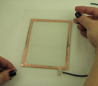
Constructing A Transparent Electrode
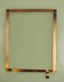
As stated previously, the transparent discharge plate is constructed from three main components; a 4" x 5" piece of glass with a transparent conductive tin oxide coating on one side, a rectangle ring electrode made from thin adhesive copper foil, that is 1/4 inch wide and 2 mils thick, and two .005 thick pieces of transparent plastic, as shown in Figure 2 below.
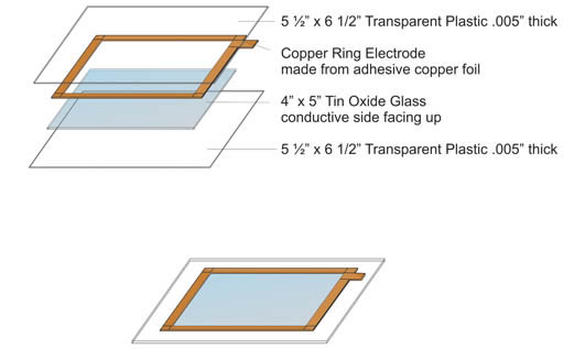
Figure 2
|
|
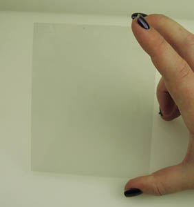
| Figure 3 - Conductive Glass |
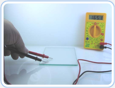
Figure 4 - Determine the tin oxide coating side of the glass |
So, to determine the tin oxide coating side of the glass you need an ohmmeter. Inexpensive VOM's (volt-ohm-meters) are available from local electrical store. Set the VOM to read OHMS on lowest resistance setting. Bring both probes in contact with one side of the transparent electrode material. The side with the conductive coating will deflect the meter, see figure below. The meter shown above(Figure 4) is on its lowest resistance setting and is showing a resistance of 165 ohms per inch.
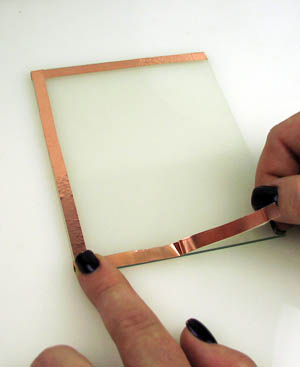
The electrode is made from thin adhesive copper foil. You can easily cut this material with a scissors.
Begin by cleaning the tin oxide glass, thoroughly so you have a good surface for the copper foil to adhere to. Re-clean the surface throughout the assembly process to ensure that no prints or lint are left on the glass.
|
|
| Figure 5 | Figure 6 |
Test assembly with an ohmmeter before proceeding. Touch the tab of the ring electrode with one probe and touch the tin oxide coating with the other. You should show good conductivity (low resistance).
Next, solder approximately 18 inches of high voltage wire to the protruding tab. the wire should lay perpendicular to the copper tab as shown in Figure 7. Try to solder the wire so that it lays as close to the glass as possible. This will connect the transparent discharge plate to the HV source when you are finished.
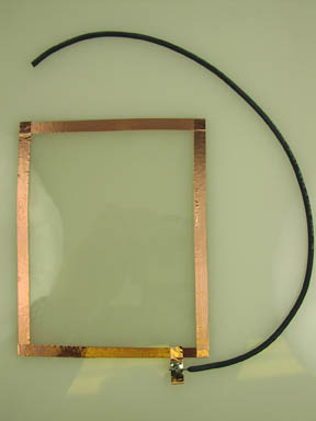
Figure 7
Since the conductive coating of the transparent electrode is delicate we need to protect it. Purchase two sheets of transparent plastic which is approximately .005 thick. Cut the plastic sheet to size adding 3/4 inch to all sides of the transparent electrode.
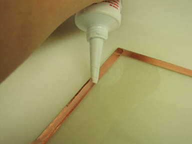
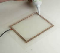
Run a thin bead of clear silicone adhesive around the edge of the transparent electrode, on top of copper foil, as shown in Figure 8. Center the plastic on top of the conductive tin oxide coating (Figure 9). Place a book or flat object onto the transparent electrode to hold the assembly tight and together while the silicone cures. Curing time is approximately 12 - 24 hours.
 |
 |
| Figure 8 - Running Bead of Silicone | Figure 9 - Center Acetate over Electrode |
Once the silicone is dry, repeat this process on the opposite side of glass by running a bead of silicone around the edge of glass and centering second piece of plastic on top of glass, as demonstrated in Figures 10 and 11. Place a book or flat object onto the transparent electrode to hold the assembly tight and together while the silicone cures. Wait another 12 -24 hours.
 |
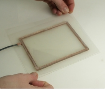 |
| Figure 10 - Running Bead of Silicone on Glass side | Figure 11 - Center Second Sheet of Acetate |
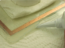
You should now have the transparent electrode sandwiched between two sheets of transparent plastic. Next, fill the gap from the edge of the glass to the outside edge of the plastic sheets with silicone adhesive, see figure 12. Place a book or flat object onto the transparent electrode once again to hold the assembly tight and together while the silicone cures. Allow to dry completely before continuing.
|
|
| Figure 12 - Fill Gap Between Acetate Sheets with Silicone | Figure 13 - Electrode Sealed in Silicone and Acetate |
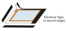
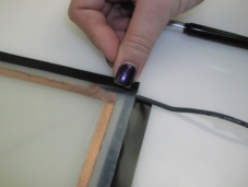
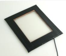
Create a frame for your transparent electrode by running black electrical tape along the edges of the transparent electrode to further secure the plastic sheets together (see Figure 14).
|
| Figure 14 - Framing Electrode |
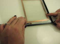
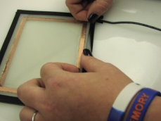
First, run the tape along the edges of the transparent electrode. When you reach the edge that has the HV wire protruding from the side, use an Exacto knife to cut a slice in the tape, so that the tape can be secured to electrode without leaving a gap. Figures 14 -18 demonstrate this process.
 |
 |
| Figure 15 - Taping Edges of Electrode | Figure 16 - Cut Slit for Wire |
 |
 |
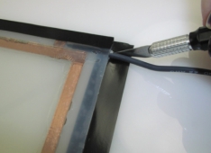
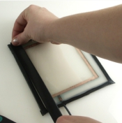
| Figure 17 - Fold up Small Piece of Tape | Figure 18 - Finish Taping Along Edge |
Then, wrap it around the glass on each side to cover the space between the edge of the electrode and where the copper foil appears, as demonstrated in Figures 19 and 20.
 |
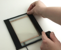 |
| Figures 19 & 20 - Wrap Tape Around Glass to Cover from Edge to Copper | |
The tape serves a dual purpose. First, it helps secure the plastic sheets to the transparent electrode. Secondly, it provides insulation along the edge of the electrode where it is needed. You may want to double tape the corner edges to provide an additional measure of insulation.
Using a Transparent Discharge Plate
The transparent electrode may be used with a variety of High Voltage power supplies provided that it has an external HV lead to connect to the transparent electrode. We take the HV using an alligator clip wire connecting to the wire or copper electrode of the high voltage power supply and connect it to the tab of the transparent electrode. Typically the camera is located on the opposite side of the working surface. Because the electrode is transparent, you can shoot through the electrode as if it were a pane of glass.
As an example, here is the procedure to shoot a leaf. In this example the leaf is at ground potential and the transparent electrode is at the HV potential. Make the set up in a room that can be made relatively light tight. The leaf is placed on a black non-reflecting, nonconductive surface. This improves background contrast. The transparent electrode is placed over the leaf. The thin plastic sheet side on the electrode is placed on the leaf. The leaf is connected to ground using by an alligator clip wire.
The camera is positioned over the assembly (see Figure above). The view through the camera should only show the object under the transparent electrode. This is accomplished with a close up lens (macro); a 4+ adapter or a reversing ring. The camera must be manually focused onto the object. If an auto-focus camera is being used set it to manual operation.
Open the aperture (f-stop) of the camera as wide as possible (2.0 or 2.4). If you are using a digital camera manually set the exposure to 10-20 seconds. If you are using a film camera, set the shutter to B (bulb) to make long timed exposures. With the shutter set to B, The shutter remains open as long as pressure is kept on the shutter. Using a shutter release cable attached to the camera will make taking pictures much easier. You can use any type of color film in the camera. I strongly advise using the fastest film available, either ISO 1000 or ISO 1600.
Manually focus the camera on the object with the room lights on. After the camera is focused, shut off all the room lights. Use a flashlight with a deep red filter to navigate around the room. When you are by the camera turn off the flashlight and open the shutter of the camera using the cable release. Now turn on the high voltage power supply. Keep the hv power supply for the length of the exposure you are making (10-20 seconds. Next release the shutter using the cable release. Turn on the room lights and set up your next picture.
Manual Kirlian Device
The technique is similar to the one mentioned above. Manually focus the camera on the object with the room lights on. After the camera is focused, shut off all the room lights. Use a flashlight with a deep red filter to navigate around the room. When you are by the camera turn off the flashlight and open the shutter of the camera using the cable release. Now pulse the switch on the manual Kirlian Device. Hit the switch 50 to 100 X to build up a strong image onto the film. Next release the shutter using the cable release. Turn on the room lights and set up your next picture.
One hint I'd like to pass along. If you are using a 35 mm film camera, start each roll of film with a few conventional pictures. This allows the photo-lab to align the frames properly on the machine. Tell the photo lab to print all frames, they may interpret the glowing outlines and corona discharges as picture errors and not print them.
The same technique described here for taking stills may also be used to film real time Kirlian video.
One may ground the object you are photographing in any number of ways. The grounding figures below illustrates two methods. The first illustration shows the ground wire directly attached to the object. When shooting like this many times the ground wire will be visible in the photograph. To remove the wire in the photograph I use the second method illustrated, a small hole is made in the black paper background. The ground wire is fed through the hole to touch the object being photographed. Resting the object on top of the ground wire, gives a nice black background and a ground for the object without any obtrusive wires. You may also use a small grounded copper plate in place of the wire as long as the object you are shooting makes contact with the plate through the hole of the black paper background.